Jumper cap

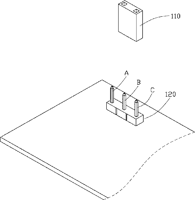
A technology of jumping caps and guides, applied in the field of jumping caps, can solve the problems of easy loss, difficulty, and small size of the jumping cap 110, and achieve the effect of avoiding plugging and unplugging operations and preventing the loss of jumping caps.

Inactive Publication Date: 2010-06-23
HONG FU JIN PRECISION IND (SHENZHEN) CO LTD +1
View PDF0 Cites 0 Cited by
  • Summary
  • Abstract
  • Description
  • Claims
  • Application Information

AI Technical Summary

Problems solved by technology

like figure 1 Shown is a schematic diagram of the state of use of the existing jumper cap 110, a connector 120 including three pins can have four connection modes: pin A and pin B are connected, pin B and pin C are connected, and all pins are not connected And pin A and pin C are connected, the first three connection methods can be realized by placing jumper cap 110 on pin A and pin B, jumper cap 110 on pin B and pin C, and without using jumper cap 110. Jumper 110 cannot connect pin A and pin C
Moreover, when there are other electronic components around the position of the connector 120, it is more difficult to insert the jumper cap 110 after taking it off, and the removed jumper cap 110 is also easy to lose due to its small size.

Method used


Image

  • Jumper cap
  • Jumper cap
  • Jumper cap

Examples


Embodiment Construction

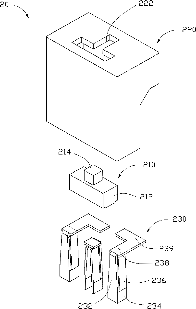
[0012] Please refer to figure 2 and image 3 A preferred embodiment of the jumper cap 20 of the present invention includes a switch 210 , a jumper cap shell 220 , and three guide pieces 230 . The number of the guide pieces 230 can be increased correspondingly according to actual needs, and only three are taken as an example for illustration in this embodiment.

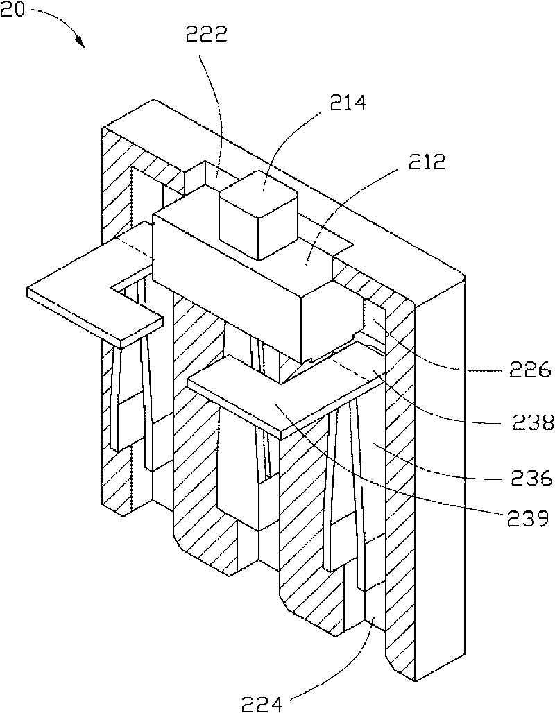
[0013] The jumper shell 220 is a square cylinder in the shape of an inverted "7", and the bottom of the jumper shell 220 is provided with three slots 224 corresponding to the pins on the motherboard connector, and the top of the slots 224 is connected. A slideway 226 is formed, and a “T”-shaped opening 222 communicating with the slideway 226 is provided on the top of the jumper cap shell 220 . Wherein, the distance between the slot holes 224 on both sides is greater than the length of the slider 212 .

[0014] The guide piece 230 is made of conductive material, which includes a connecting body 232, the lower side e...


PUM


Abstract

A jumper cap is used for controlling the connection between the pins of a connector, which comprises a jumper cap shell, a transfer switch and a plurality of electrical conductivity patches corresponding to the pins of the connector, wherein the jumper cap shell is correspondingly provided with slots for holding the electrical conductivity patches; the bottom of the electrical conductivity patch can be electrically connected with the corresponding pin of the connector; the tops of two spaced electrical conductivity patches are respectively formed with an extending part on the same side in an extending way, and the two extending parts are not connected; the tops of the slots are communicated to form a slideway; and the transfer switch is movably arranged in the slideway and can be electrically connected with two adjacent conductivity patches or the extending parts of the two spaced conductivity patches. The jumper cap can conveniently control the connection between the pins of the connector of the computer mainboard.

Description

technical field [0001] The invention relates to a jumper cap, in particular to a jumper cap used for controlling the mutual connection between pins of a connector on a computer motherboard. Background technique [0002] There are usually connectors on the motherboard of the computer that can be set by the user. This type of connector includes a number of pins on the motherboard and jumpers for the user to set which pins are connected to each other. Such as figure 1 Shown is a schematic diagram of the state of use of the existing jumper cap 110, a connector 120 including three pins can have four connection modes: pin A and pin B are connected, pin B and pin C are connected, and all pins are not connected And pin A and pin C are connected, the first three connection methods can be realized by placing jumper cap 110 on pin A and pin B, jumper cap 110 on pin B and pin C, and without using jumper cap 110. The jumper cap 110 cannot realize the connection of pin A and pin C. Mor...

Claims


Application Information

Patent Timeline
Patent Type & Authority Applications(China)
IPC IPC(8): H01R31/08
CPCH01R13/70H01H25/002H01R31/08H01H15/005
Inventor 孙正衡马小峰
Owner HONG FU JIN PRECISION IND (SHENZHEN) CO LTD
Why Eureka
Try Eureka