
A wind wheel locking device and wind wheel

A technology of locking device and wind wheel, applied in wind power generation, wind power engine, engine, etc., can solve problems such as sticking, locking pin 22 is not easy to pull out, etc., and achieves the effect of solving easy sticking and avoiding plugging action

Active Publication Date: 2021-08-24
SANY ELECTRIC CO LTD
View PDF1 Cites 0 Cited by
  • Summary
  • Abstract
  • Description
  • Claims
  • Application Information

AI Technical Summary

Problems solved by technology

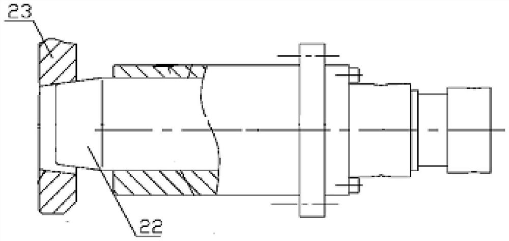
When the device locks the fan for a long time, because the wind wheel will shake when it is in the locked state, the existing locking disc 23 and the locking pin 22 will repeatedly contact. When the repeated contact time is too long, the locking pin 22 and the existing locking pin will be locked Between the two parts of the disk 23, the edge of the right pin hole of the existing locking disk 23 will be plastically deformed due to extrusion, and an indentation will be formed between the two to cause a gap between the locking pin 22 and the existing locking disk 23. The stagnation phenomenon will cause the phenomenon that the lock pin 22 is not easy to pull out

Method used


Image

  • A wind wheel locking device and wind wheel
  • A wind wheel locking device and wind wheel
  • A wind wheel locking device and wind wheel

Examples


Embodiment Construction

[0023] In order to make the purpose, technical solutions and advantages of the embodiments of the present invention clearer, the technical solutions in the embodiments of the present invention will be clearly and completely described below in conjunction with the drawings in the embodiments of the present invention. Obviously, the described embodiments It is a part of embodiments of the present invention, but not all embodiments. The components of the embodiments of the invention generally described and illustrated in the figures herein may be arranged and designed in a variety of different configurations.

[0024] Accordingly, the following detailed description of the embodiments of the invention provided in the accompanying drawings is not intended to limit the scope of the claimed invention, but merely represents selected embodiments of the invention. Based on the embodiments of the present invention, all other embodiments obtained by persons of ordinary skill in the art wi...


PUM


Abstract

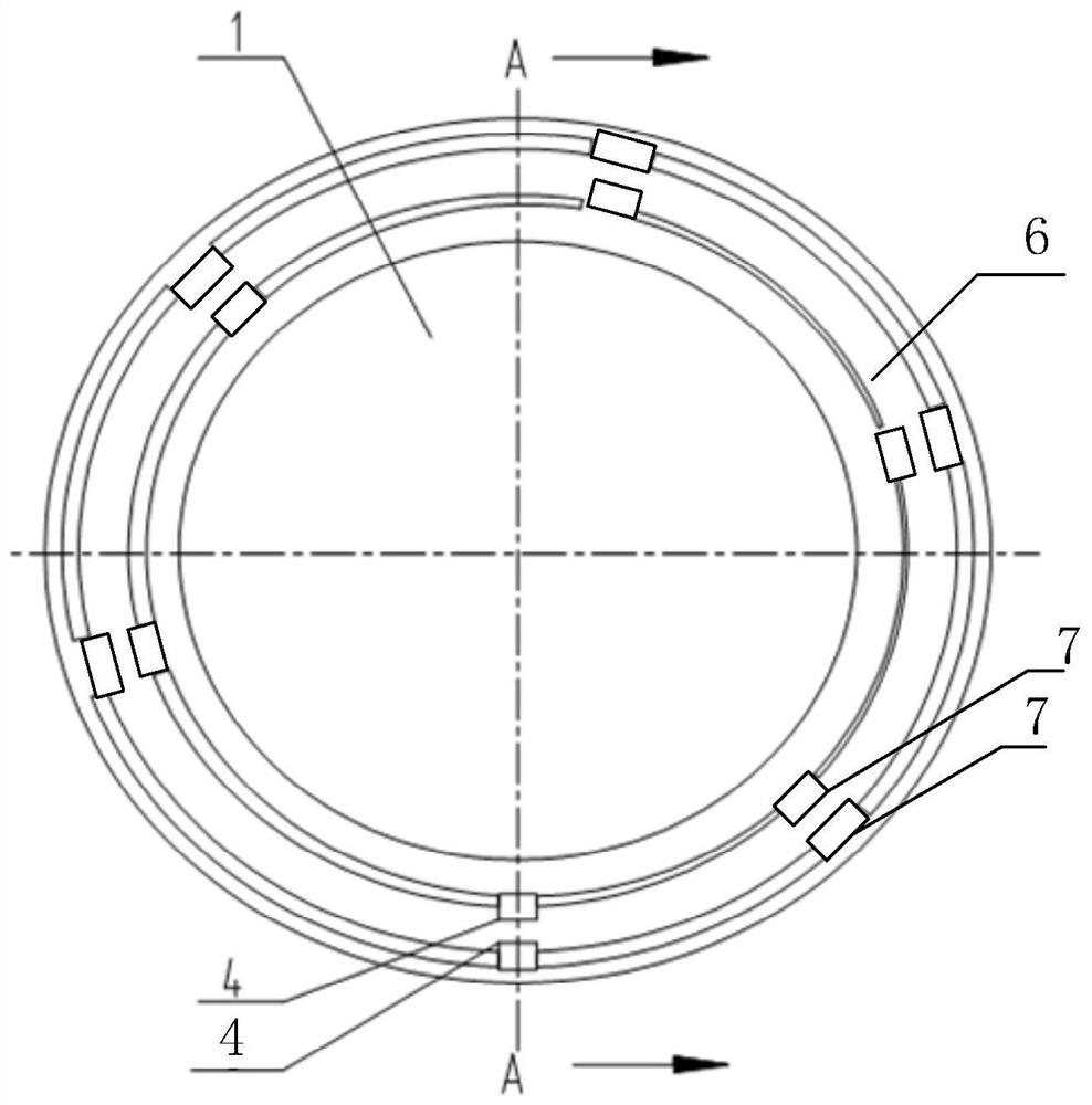
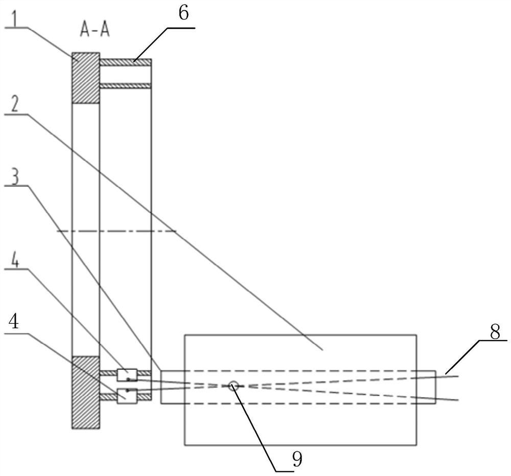
The invention provides a wind rotor locking device and a wind rotor, which belong to the technical field of wind power generation, and include a locking disc and a support assembly, the locking disc is used for fixed connection with the wind rotor of the fan, and the disc surface of the locking disc An annular track is formed in the upper circumferential direction, and the two supporting ends of the support assembly are clamped with the annular track along the radial direction of the locking disk, so as to lock the rotation of the wind wheel relative to the support assembly. The two ends of the support assembly move in the radial direction of the locking disc to realize the locking of the wind wheel, which avoids the axial insertion and extraction of the wind wheel lock pin in the prior art, and solves the problem of the wind wheel lock pin in the prior art. Easy to stick issues.

Description

technical field [0001] The invention relates to the technical field of wind power generation, in particular to a wind wheel locking device and a wind wheel. Background technique [0002] At present, most of the locking pins of the wind rotor adopt a pin-hole structure or a spline structure that can be inserted and pulled out along the direction of the main shaft of the wind rotor to realize the locking function of the wind rotor when the fan is shut down for maintenance. However, if the maintenance time of the fan is too long, or the fan is shut down for a long time, it will often cause the lock pin to get stuck. [0003] For example, patent CN102251936B discloses a fan and its wind wheel locking device, its structure is as follows: figure 1 As shown, the device realizes the locking function of the wind wheel by inserting or pulling out the locking hole of the locking disc along the direction of the main shaft. figure 1 The middle lock pin 22 can be stretched out or retrac...

Claims


Application Information

Patent Timeline
Patent Type & Authority Patents(China)
IPC IPC(8): F03D80/50F03D80/00
CPCF03D80/00F03D80/50Y02E10/72
Inventor 张文超武胜飞梁国仲
Owner SANY ELECTRIC CO LTD
Learn More