
Bidirectional coaxial reducer motor

A technology of deceleration motor and deceleration mechanism, applied in electrical components, electromechanical devices, electric components, etc., can solve the problems of large size, loss of superiority, and low efficiency

Inactive Publication Date: 2010-06-23
YANGZHOU DEBUT TECH DEV
View PDF3 Cites 12 Cited by
  • Summary
  • Abstract
  • Description
  • Claims
  • Application Information

AI Technical Summary

Problems solved by technology

Such as: coaxial double-speed output planetary gear reducer motor (patent number: ZL200620047765.1), cycloid reducer motor (application number: 07116741.6), etc.; however, although these inventions can make the motor shaft and the decelerated output shaft coaxial , but it is not allowed to have coaxial and synchronous output shafts at both ends of the geared motor, that is, bidirectional, coaxial, and synchronous output shafts, because the structural characteristics of the motor itself determine the technical difficulty of realizing this function. In order to solve this problem, the usual method is to transmit power to the end of the motor through various transmission methods. Although this can be achieved in mechanical transmission design, the huge transmission mechanism brings large volume, high cost, and Many shortcomings such as low efficiency make such a design itself lose its superiority

Method used


Image

  • Bidirectional coaxial reducer motor
  • Bidirectional coaxial reducer motor
  • Bidirectional coaxial reducer motor

Examples


Embodiment 1

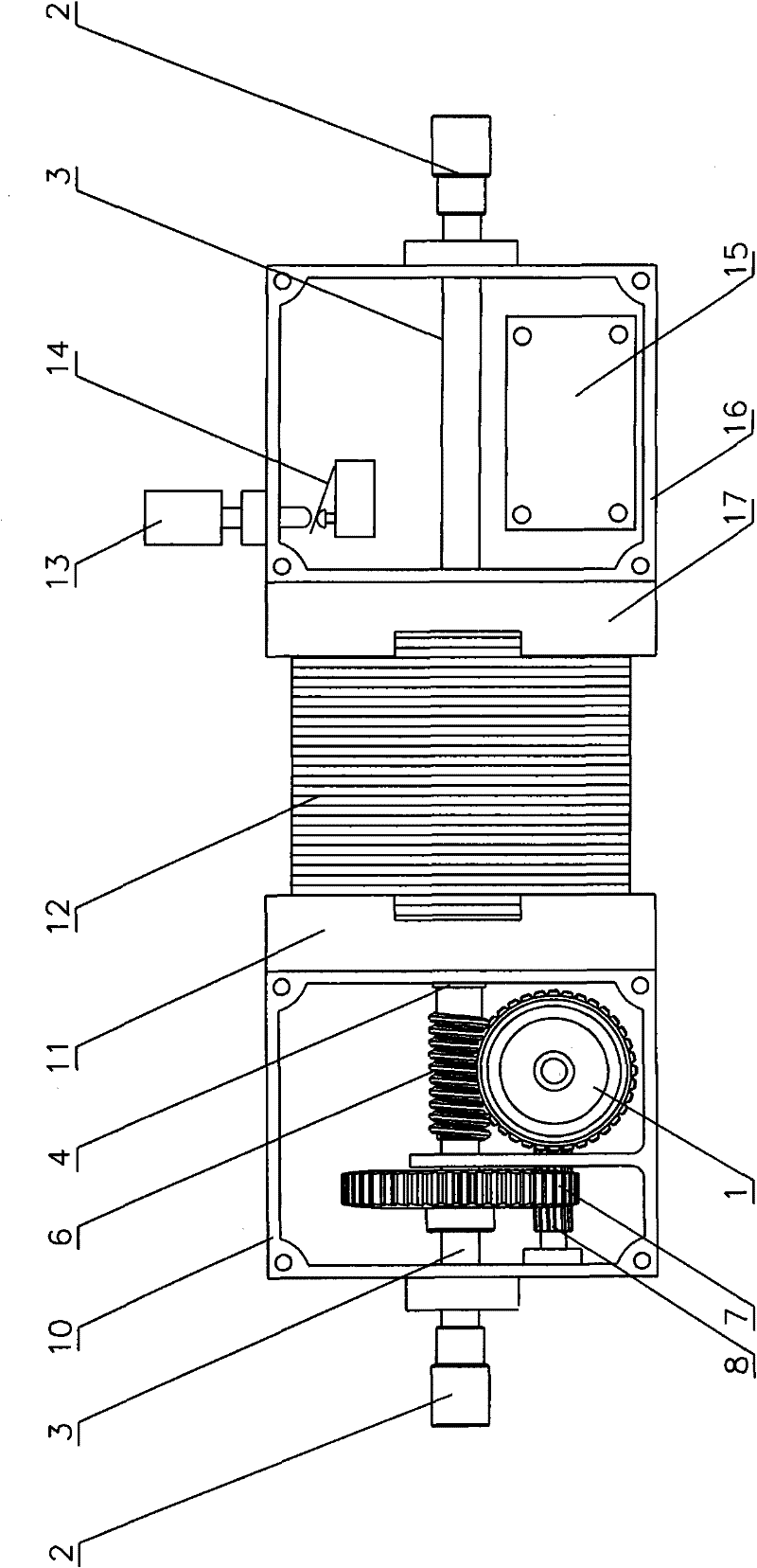
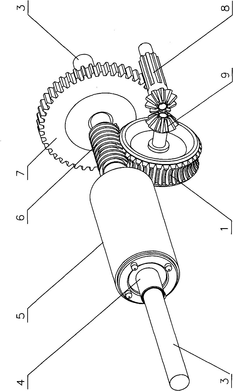
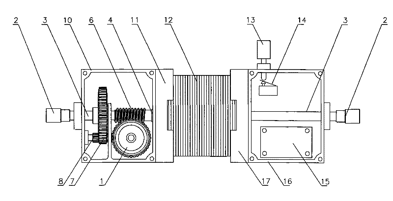
[0016] As shown in the figure, a left end cover (11) and a right end cover (17) are installed at both ends of the motor stator group (12), a reduction box (10) is installed on the left end cover (11), and a right end cover (17) ) is equipped with electrical control box (16), these two casings all have the installation hole that position is coaxial with rotating shaft and output shaft, and bearing is installed in the hole.

[0017] The motor rotor (5) is installed in the motor stator group (12), and in the motor rotor (5), there is a through-hole shaft (4) assembled as a whole, and the longer end of the through-hole shaft (4) is processed into a worm (6), and the through-hole shaft (4) become an integral shaft with a through hole; a worm wheel (1), a large spur gear (7), a spur bevel gear (8) and an umbrella are installed in the reduction box (10) The gear (9) and the through-hole shaft (4) with the worm (6) form a worm gear reduction mechanism. The installation position of the...

Embodiment 2

[0022] The difference from Example 1 is that if there is a higher requirement for the deceleration performance of the deceleration motor, other types and structural forms of deceleration mechanisms can be used to achieve the purpose of deceleration. The longer end of the motor rotor through-hole shaft is a worm or gear. And in the design of the reduction mechanism, the position of the output shaft coaxial with the through-hole shaft of the motor rotor is reserved, so that the output shaft can pass through the through-hole shaft of the motor rotor, thereby realizing the power output function of bidirectional coaxiality. If there are requirements for the type and performance of the motor used, the motor needs to be specially designed, but the motor rotor must be a through-hole shaft. Because other types and structural forms of the reduction mechanism have their own characteristics in their structures, they are relatively complicated to implement, the volume will become larger, an...


PUM


Abstract

The invention relates to a bidirectional coaxial reducer motor. Output shafts arranged at both ends of the reducer motor are coaxial and can output power synchronously. A rotary shaft of a motor rotor in the reducer motor is a through hole shaft one longer end of which is a worm or a gear; during rotation, the rotor drives a reducing mechanism in a reducing gearbox to reduce speed of the output shafts which are coaxial with the motor rotor and pass through the through hole on the rotor; the speed-reduction box and an electrical appliance control box are respectively located at both ends of the axial direction of the motor to form an integrity; and the output shafts extend from both ends of the speed-reduction box and the electrical appliance control box so as to realize the functions of bidirectional,coaxial and synchronous output of power after speed reduction.

Description

1. Technical field [0001] The invention relates to a geared motor, in particular to a bidirectional coaxial geared motor. 2. Background technology [0002] There are many types of reducers, including helical gear reducers (including parallel shaft helical gear reducers, worm gear reducers, bevel gear reducers, etc.), planetary gear reducers, cycloidal pin wheel reducers, worm gear reducers , Planetary friction mechanical stepless speed changer, etc., are decelerated by connecting the motor. After the motor and the reducer are designed as a whole, it is a geared motor. Due to its integrated design, it achieves better performance and at the same time brings great convenience to users. Among them, the worm gear motor is the more commonly used one. [0003] The worm gear motor is designed based on the principle of worm gear transmission. In addition to deceleration, the worm gear transmission mechanism can also rotate forward and reverse frequently. The elevators seen in daily...

Claims


Application Information

Patent Timeline
IPC IPC(8): H02K7/116
Inventor 徐德宏
Owner YANGZHOU DEBUT TECH DEV
Learn More