Cleaner

A cleaning device and cleaning liquid technology, which is applied in the field of sanitary cleaning tools, can solve the problem that the cleaning liquid outlet cannot be arbitrarily reversed and the needs of different people are convenient to use, and achieve the effect of convenient use

Inactive Publication Date: 2010-06-30
韦锋
View PDF0 Cites 0 Cited by
  • Summary
  • Abstract
  • Description
  • Claims
  • Application Information

AI Technical Summary

Problems solved by technology

[0002] The structure of the commonly used sanitation cleaning tools has a common disadvantage that the outlet of the cleaning solution cannot be twisted arbitrarily to meet the needs of different people for easy use

Method used


Image

  • Cleaner
  • Cleaner
  • Cleaner

Examples


Embodiment Construction

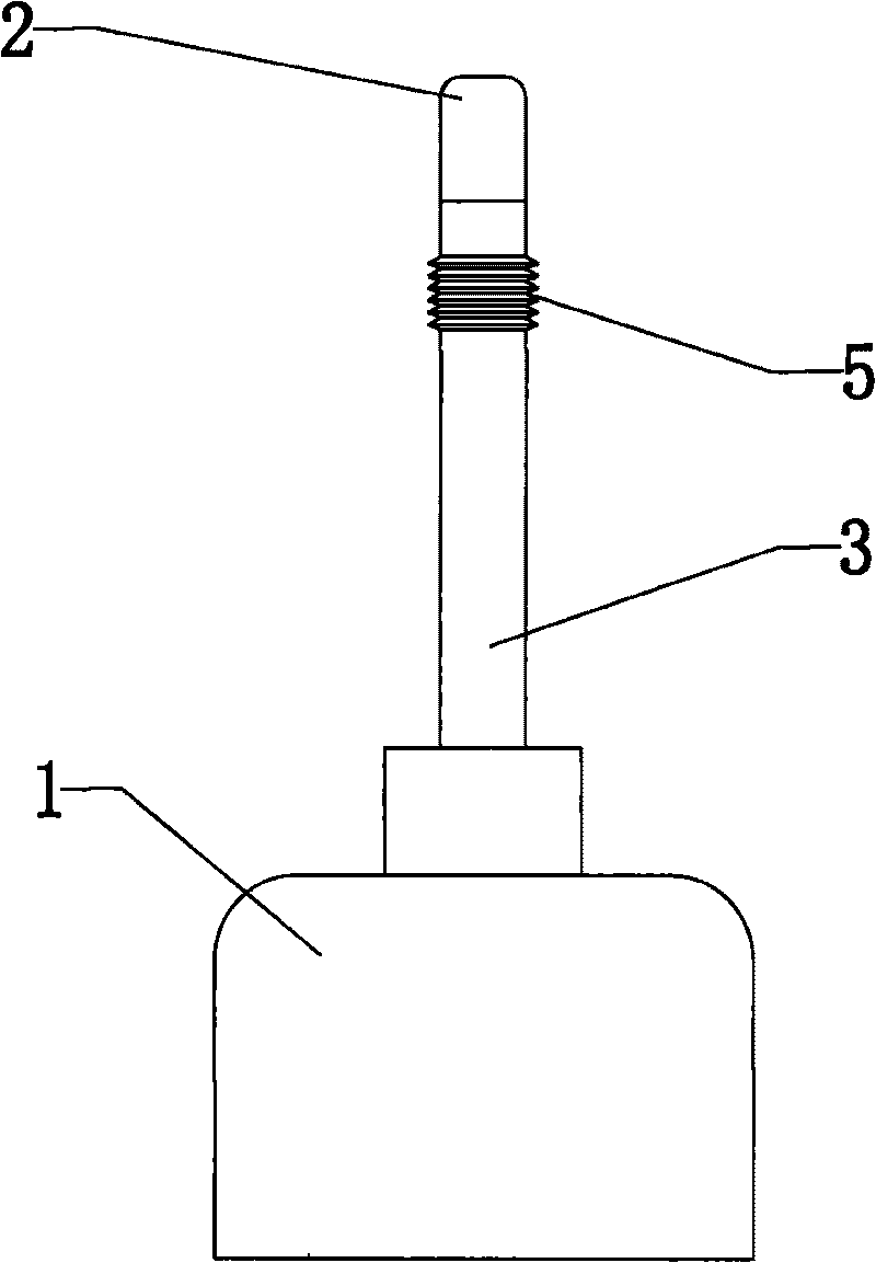
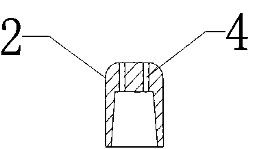
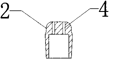
[0013] like Figure 1-3 As shown, the cleaning device of the present invention is installed on the barrel body 1 containing the cleaning liquid, and includes a body 3 and a nozzle 2 installed on the body 3. The nozzle 2 is evenly provided with a number of small holes 4. On the body One end close to the nozzle 2 is provided with a plastic tube 5, and the plastic tube 5 is stacked into a number of V-shaped rings connected in sequence, so that when the plastic tube 5 encounters an external force, it will be twisted into a certain angle to adapt to the user's cleaning. At the same time, the plastic tube 5 can be automatically fixed, that is to say, it will stay on the effect of the previous external force before encountering the next external force. A layer inlet connection port can be provided on the outside or inside of the spray head 2 to connect with the body 3 to ensure the sealing of the washer.


PUM


Abstract

The invention discloses a cleaner, which is arranged on a bucket filled with cleaning solution and comprises a body and a spray head arranged on the body, wherein the spray head is provided with a plurality of pores uniformly, and a plastic pipe is arranged at one end of the body near the spray head and folded into a plurality of V-shaped rings connected in sequence. The cleaner has the benefits that the spray head can be turned freely to adapt to different needs through the plastic pipe, and the turned spray head can not automatically return to the original direction, therefore, the use is very convenient.

Description

technical field [0001] The invention relates to a hygienic cleaning tool, in particular to a washer. Background technique [0002] The structure of the commonly used sanitary cleaning tools has a common shortcoming in that the outlet of the cleaning solution cannot be twisted arbitrarily to meet the needs of different people for easy use. Contents of the invention [0003] The purpose of the present invention is to provide a washer, the outlet position of the cleaning liquid can be twisted arbitrarily to meet the needs of different people. [0004] The purpose of the present invention is to realize through the following technical solutions: [0005] A washer, installed on a bucket body filled with cleaning liquid, including a body and a nozzle installed on the body, a number of small holes are uniformly arranged on the nozzle, and a plastic tube is arranged on the end of the body near the nozzle. The plastic tubes are stacked into several V-shaped rings connected in sequ...

Claims


Application Information

Patent Timeline
IPC IPC(8): B05B11/00B65D47/06B08B3/00
Inventor 韦锋
Owner 韦锋
Why Eureka
Try Eureka