
Flat knitting machine

A technology of flat knitting machine and machine head, which is applied in the direction of flat knitting machine with separate action needle, textile and paper making, weft knitting, etc. problem, to reduce friction and reduce pressure

Inactive Publication Date: 2010-06-30
WUJIANG CITY HONGHUI APPAREL
View PDF0 Cites 0 Cited by
  • Summary
  • Abstract
  • Description
  • Claims
  • Application Information

AI Technical Summary

Problems solved by technology

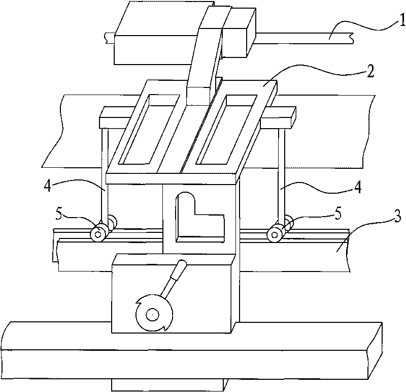
[0002] The flat knitting machine mainly includes a guide rail and a machine head slidingly arranged on the guide rail. The weight of the machine head is usually heavy, which makes the friction between the machine head and the guide rail relatively large. Whether it is an automatic flat knitting machine or a manual flat knitting machine, it is necessary to drive The machine head needs to spend a lot of effort, and the whole device is relatively cumbersome

Method used


Image

  • Flat knitting machine
  • Flat knitting machine

Examples


Embodiment Construction

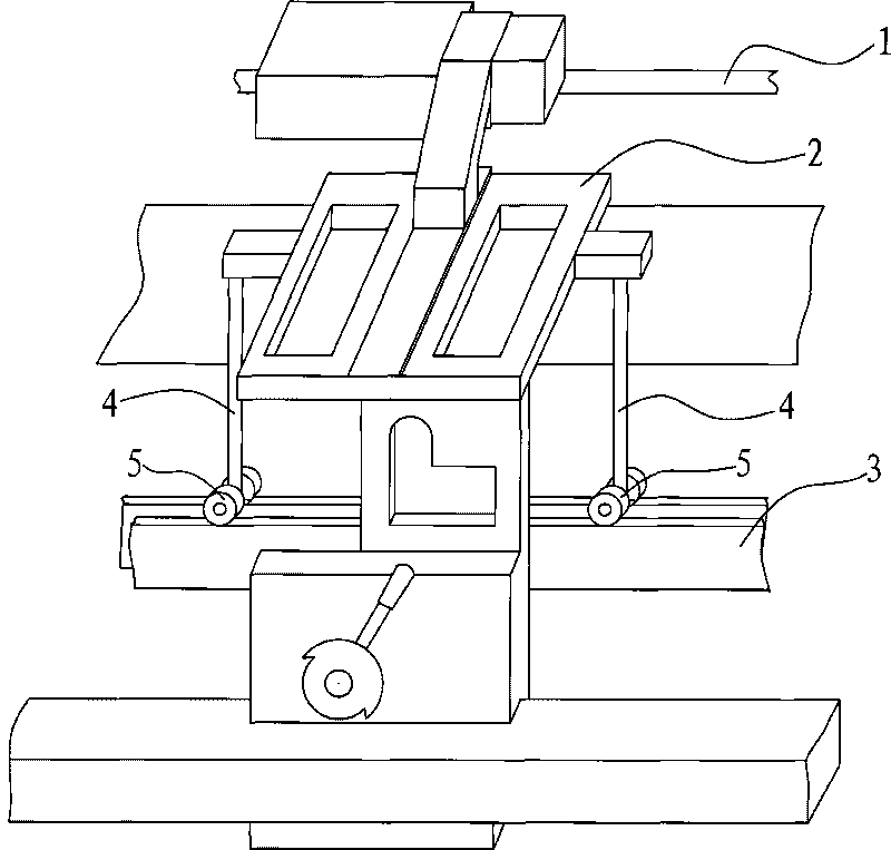
[0008] The specific embodiment of the present invention is described below: a kind of flat knitting machine, comprises guide rail 1, the machine head 2 that is slidably arranged on described guide rail 1, also comprises slide rail 3, symmetrically fixed on the two sides of described machine head 2 The two supports 4 are rotated and arranged on the rollers 5 at the bottom of each of the supports 4, and the rollers 5 are rollingly supported on the slide rails 3. The roller 5 supports the weight of the nose 2, reduces the pressure between the nose 2 and the guide rail 1, and then reduces the friction between the nose 2 and the guide rail 1; There is rolling friction between the rails 3, and the frictional resistance is very small, so the frictional force of the whole flat knitting machine can be greatly reduced, no matter for the automatic flat knitting machine or the manual flat knitting machine, the operation is labor-saving.


PUM


Abstract

The invention relates to a flat knitting machine, comprising a guide rail, a nose arranged on the guide rail in a sliding way, a sliding rail, a bracket arranged on the nose, and rollers arranged on the bottom end of the bracket in a rotating way. The rollers are supported on the sliding rail in a rolling way. By adopting the technical scheme, compared with the prior art, the invention has the advantages that the rollers are supported on the sliding rail in a rolling way, thereby the pressure and friction between the guide rail and the nose are reduced and the nose glides easily relative to the guide rail.

Description

technical field [0001] The present invention relates to improvements to flat knitting machines for sweater knitting. Background technique [0002] The flat knitting machine mainly includes a guide rail and a machine head slidingly arranged on the guide rail. The weight of the machine head is usually heavy, which makes the friction between the machine head and the guide rail relatively large. Whether it is an automatic flat knitting machine or a manual flat knitting machine, it is necessary to drive The machine head all needs to expend greater strength, and the whole device seems relatively bulky. Contents of the invention [0003] The technical problem to be solved by the invention is to reduce the frictional force between the machine head and the guide rail, so that the operation of the flat knitting machine is labor-saving. [0004] In order to achieve the above object, the technical solution adopted by the present invention is: a flat knitting machine, comprising a gui...

Claims


Application Information

Patent Timeline
IPC IPC(8): D04B15/00D04B7/00
Inventor 蒋雨雨
Owner WUJIANG CITY HONGHUI APPAREL
Learn More