Omnidirectional rotating lamp

An all-round, lighting technology, applied in the direction of electric light circuit layout, lighting device components, lighting and heating equipment, etc., can solve the problems of inconvenient operation, unsafe, complex structure, etc., to achieve convenient use, reasonable structure, and reduce occupancy. large space effect

Inactive Publication Date: 2010-06-30
OCEANS KING LIGHTING SCI&TECH CO LTD +1
View PDF0 Cites 15 Cited by
  • Summary
  • Abstract
  • Description
  • Claims
  • Application Information

AI Technical Summary

Problems solved by technology

However, at present, the adjustment of the lighting direction of the lamp is adjusted by manual movement. After the adjustment is completed, it is fixed by tooth groove positioning and screw tightening. Manual adjustment is troublesome, and even requires high-altitude operations, which is very unsafe. Usually only one-way manual orientation can be achieved
Another way is to adjust the irradiation direction through a rotating mechanism. The rotating mechanism uses a motor acceleration and deceleration box to complete the rotation in one direction. If you want to achieve full rotation in more than two directions, you need to use multiple motors Coupled with multiple rotating mechanisms, this structure has caused the problems of large volume, complex structure and inconvenient operation of the lamp

Method used


Image

  • Omnidirectional rotating lamp
  • Omnidirectional rotating lamp
  • Omnidirectional rotating lamp

Examples


Embodiment 1

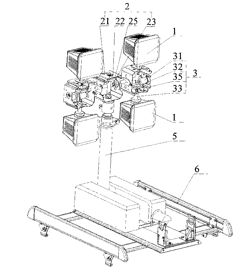
[0023] Example 1, such as figure 1 , 2 , 3, a lamp that rotates in all directions, includes a lamp body 1, and the lamp body 1 is connected with a pan-tilt mechanism that drives it to realize omni-directional rotation, and the pan-tilt mechanism includes a control device (not shown in the figure), At least two pan-tilts that are rotatably connected together, one of which is the main pan-tilt 2, and the rest of the pan-tilts are auxiliary pan-tilts 3, the auxiliary pan-tilt 3 is rotatably connected with the lamp body 1 to drive the lamp body to rotate 360°, the main The pan-tilt 2 and the auxiliary pan-tilt 3 are rotationally connected to drive the auxiliary pan-tilt 3 to rotate 360°, the main pan-tilt 2 and the auxiliary pan-tilt 3 are connected to the control device, and the main pan-tilt housing 21 is provided with a support frame 5 and a base 6 .

[0024] like figure 1 , 4 , shown in 5, main platform 2 comprises main platform housing 25, is provided with main platform m...

Embodiment 2

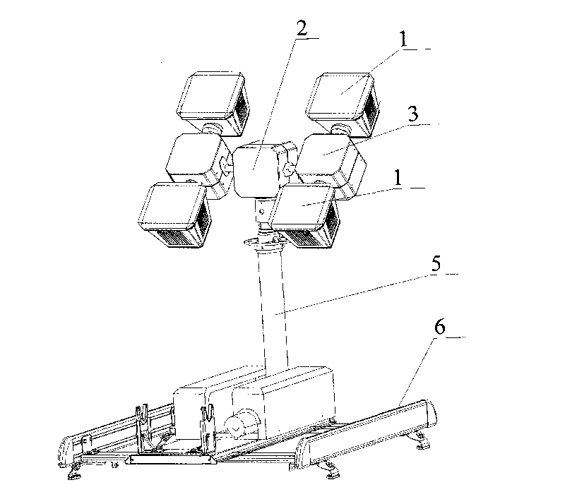
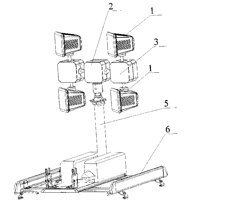
[0029] Embodiment 2, as Figure 6 As shown, it is a structural schematic diagram of two lamp bodies, one main pan-tilt, and one auxiliary pan-tilt. The auxiliary cloud platform rotating shaft 33 is vertically arranged, and its upper and lower ends are fixedly connected with one or more lamp bodies 1 respectively. The lamp body 1 operates synchronously. The middle part of the auxiliary cloud platform rotating shaft 33 is meshed with the gear in the auxiliary cloud platform reduction box 32 . The main cloud platform rotation shaft 23 is horizontally arranged, and one end thereof is fixedly connected with the auxiliary cloud platform housing 33, and the other end is engaged with the gear in the main cloud platform reduction box 22, and the auxiliary cloud with the gear engagement in the auxiliary cloud platform reduction box 32 The table rotating shaft 33 rotates to drive the lamp body 1 to rotate 360° in the horizontal direction, and the direction of rotation can be clockwise ...


PUM


Abstract

The invention discloses an omindirectional rotating lamp which comprises a lamp main body connected with a holder mechanism. The holder mechanism which drives the lamp main body to realize omindirectional rotation comprises a control device and at least two holders, wherein the two holders are connected together in a rotating manner, one is a main holder, and the other is an auxiliary holder. The auxiliary holder is connected with the lamp main body in a rotating manner to drive the lamp main body to rotate at 360 DEG, and the main holder is connected with the auxiliary holder in a rotating manner to drive the auxiliary holder to rotate at 360 DEG. Both the main holder and the auxiliary holder are connected with the control device which respectively controls rotating angles of the lamp main body and the auxiliary holder in two vertical directions. The provided omindirectional rotating lamp has the advantages of simple structure, small volume, simple as well as convenient operation, no dead corners for irradiation and omindirectional adjustment.

Description

technical field [0001] The invention relates to a lamp, in particular to an omnidirectional rotating lamp. Background technique [0002] In many occasions, it is necessary to frequently adjust the irradiation position and direction of the lamp. In order to realize the all-round rotation of the lamp without obstacles, it is required that the lamp can be rotated 360° in two directions perpendicular to each other. However, at present, the adjustment of the lighting direction of the lamp is adjusted by manual movement. After the adjustment is completed, it is fixed by tooth groove positioning and screw tightening. Manual adjustment is troublesome, and even requires high-altitude operations, which is very unsafe. Also usually only one-way manual orientation can be achieved. Another way is to adjust the irradiation direction through a rotating mechanism. The rotating mechanism uses a motor acceleration and deceleration box to complete the rotation in one direction. If you want to...

Claims


Application Information

Patent Timeline
Patent Type & Authority Applications(China)
IPC IPC(8): F21V19/00F21V23/00H05B37/02F21S2/00
Inventor 周明杰吴晓兵何其猛李植海曾武黄剑云
Owner OCEANS KING LIGHTING SCI&TECH CO LTD
Why Eureka
Try Eureka