Direction operating mechanism for intelligent body building vehicle
A technology of direction control and exercise bike, applied in gymnastics equipment, training equipment for adjusting coordination, training equipment for adjusting cardiovascular system, etc., can solve the problems of complex structure, rising production cost, simple structure, etc., and achieve accurate signal acquisition , Low production cost, easy to achieve effect
- Summary
- Abstract
- Description
- Claims
- Application Information
AI Technical Summary
Problems solved by technology
Method used
Image
Examples
Embodiment 1
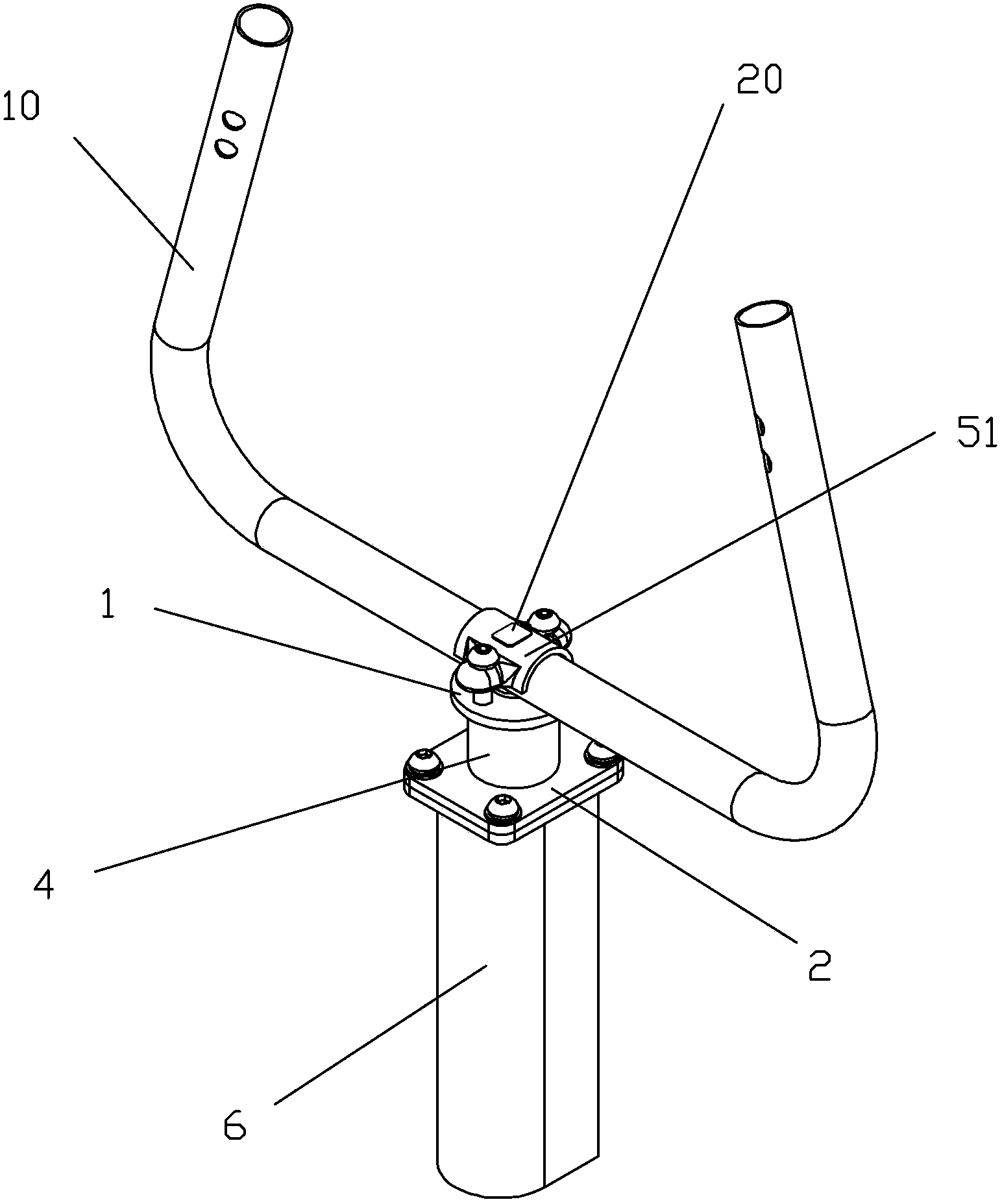
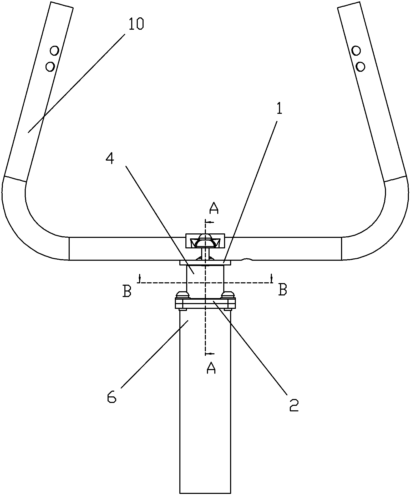
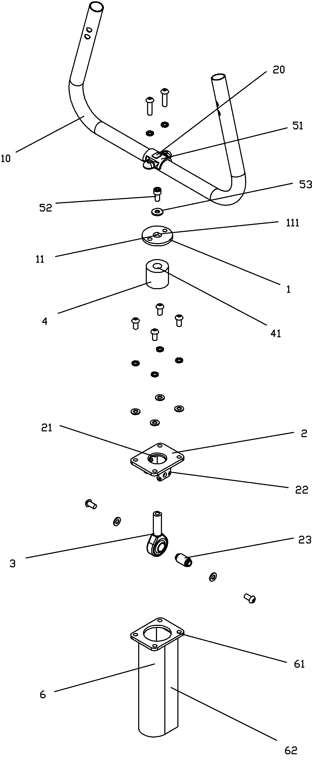
[0040] Embodiment one, see Figure 1 to Figure 8 Shown, the direction manipulation mechanism of a kind of intelligent exercise bike of the present invention comprises:
[0041] An upper fixing plate 1 that can be fixed to the handlebar 10 of the smart exercise bike;
[0042] A lower fixing plate 2 that can be fixed to the frame of the smart exercise bike;
[0043] A rod end joint bearing 3, including a rod end 31 and a support body 32 that supports the rod end to swing 360 degrees in all directions;
[0044] An elastic body 4 that can realize reset;
[0045] The support body 32 of the rod end joint bearing is connected and fixed with the lower fixing plate 2, the rod end 31 of the rod end joint bearing is connected and fixed with the upper fixing plate 1 through the elastic body 4, and the elastic body 3 supports the upper fixing plate 1 and the upper fixing plate 1. between the lower fixing plates 2, so that the handlebar 10 connected to the upper fixing plate 1 can realize ...
Embodiment 2
[0054] Embodiment two, see Figure 9 to Figure 15 As shown, the direction control mechanism of a smart exercise bike of the present invention differs from Embodiment 1 in that the rod end joint bearing 3 is a ball joint rod end joint bearing, and the inner ring of the bearing becomes an inner ball joint , the ball end rod end joint bearing 3 includes a rod end 31, an inner ball head 34 and a bearing outer ring 35, the support body is a bearing outer ring 35, and the rod end 31 and the inner ball head 34 are connected as one; the lower fixing plate 2 Also be provided with the second through hole 21 that can allow described rod end to pass through, and this second through hole is smaller than described bearing outer ring 35; Lower fixing plate 2 is also provided with annular convex wall 24 downwards, and described bearing outer ring 35 fits in the annular convex wall 24, and the annular convex wall is also locked with screws capable of pushing against the bearing outer ring 35. ...
PUM
 Abstract
Description
Claims
Application Information
 - R&D
- Intellectual Property
- Life Sciences
- Materials
- Tech Scout
- Unparalleled Data Quality
- Higher Quality Content
- 60% Fewer Hallucinations
Browse by: Latest US Patents, China's latest patents, Technical Efficacy Thesaurus, Application Domain, Technology Topic, Popular Technical Reports.
© 2025 PatSnap. All rights reserved.Legal|Privacy policy|Modern Slavery Act Transparency Statement|Sitemap|About US| Contact US: help@patsnap.com


