
Oil-retaining structure inside bearing pad machine for large-scale turbogenerator rotor dynamic balance test

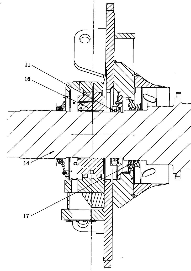
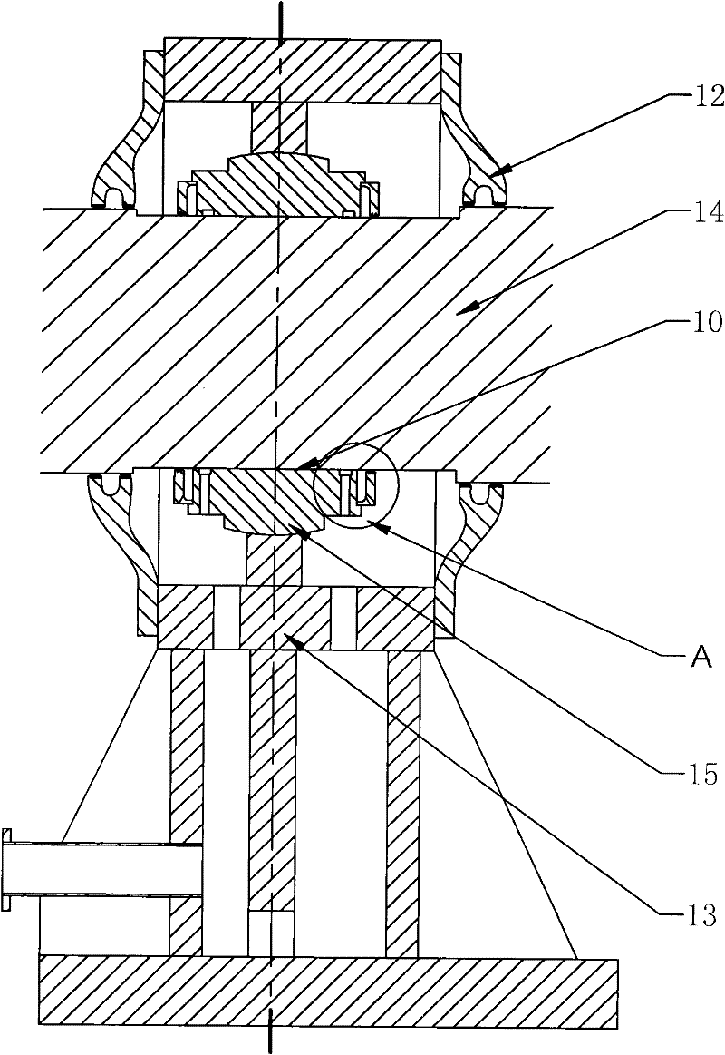
A dynamic balancing technology for turbogenerators and rotors, which is applied in static/dynamic balance testing, engine testing, machine/structural components testing, etc., and can solve problems such as oil leakage and lack of oil retaining structures

Active Publication Date: 2012-02-08
HARBIN ELECTRIC MASCH CO LTD
View PDF0 Cites 0 Cited by
  • Summary
  • Abstract
  • Description
  • Claims
  • Application Information

AI Technical Summary

Problems solved by technology

[0005] When the test bearing pad (15) is in operation, there is no sealing pad (11) on the inner side of the machine, but it is directly adjacent to the inner test oil retaining cap (12), so since the test bearing pad (15) itself does not have an oil retaining structure, Just make the oil leakage phenomenon often take place on the inner side of the bearing during the test, even if the installation requirements of the test oil retaining cap (12) are improved, this problem cannot be solved

Method used


Image

  • Oil-retaining structure inside bearing pad machine for large-scale turbogenerator rotor dynamic balance test
  • Oil-retaining structure inside bearing pad machine for large-scale turbogenerator rotor dynamic balance test
  • Oil-retaining structure inside bearing pad machine for large-scale turbogenerator rotor dynamic balance test

Examples


Embodiment Construction

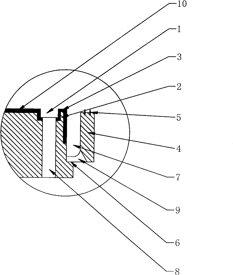
[0020] like image 3 The present invention shown is a large turbogenerator rotor dynamic balance test bearing pad machine inner oil retaining structure, the test bearing pad 15 is installed on the inner side of the machine adjacent to the test bearing pad bearing surface 10, and the outer end of the test bearing pad bearing surface 10 is an oil drain groove 1. There is a first oil discharge hole 8 at the bottom of the oil drain tank 1, and the test bearing body outside the oil drain tank 1 forms an oil retaining platform 2, and the surface of the oil retaining platform 2 has a tungsten gold structure layer 3, and a small stopper is assembled on the end surface of the test bearing shell 15 The oil cover 4, the copper comb teeth 5 inlaid with the small oil retainer 4, the upper stop 6 between the small oil retainer 4 and the test bearing bush 15, the first oil discharge hole 8 at the bottom of the oil drain groove 1, the small oil retainer An oil drain chamber 7 is formed betwee...


PUM


Abstract

The invention relates to an oil retaining structure inside a bearing pad machine for a large steam turbine generator rotor dynamic balance test. It includes the oil drain groove and the oil retaining platform inside the test bearing bush machine, the tungsten gold structure on the surface of the oil drain groove and the oil retaining platform, the small oil retaining cover assembled to the inner side of the test bearing bush machine, the copper comb inlaid with the small oil retaining cover, the small retaining plate The structure of the seam positioning between the oil cover and the test bearing. The application of the oil-retaining structure of the test bearing pad of the present invention greatly relaxes the installation requirements of the test bearing than before, but the oil-retaining effect is significantly improved than before, and no oil leakage has ever occurred.

Description

Technical field: [0001] The invention relates to an oil retaining structure on the inner side of a test bearing pad machine for dynamic balancing of a large steam turbine generator rotor. technical background: [0002] A test bearing is required during dynamic balancing of a large steam turbine generator rotor, which includes a test bearing seat (13), a test bearing bush (15), and a test oil retaining cover (12). The function of the test oil retaining cap (12) in the test bearing is to prevent the bearing lubricating oil formed in the oil film between the test bearing pad bearing surface (10) and the main shaft (14) from leaking to the outside of the bearing, but the oil retaining structure in the test bearing pad (15) The design also plays a considerable role in preventing the leakage of lubricating oil. [0003] In the past, the test bearing pad (15) used for dynamic balancing of large turbogenerators had the same structure and size as the product bearing pad (16). The s...

Claims


Application Information

Patent Timeline
Patent Type & Authority Patents(China)
IPC IPC(8): G01M1/14G01M15/02
Inventor 刘俊英刘昱光刘超
Owner HARBIN ELECTRIC MASCH CO LTD
Learn More