
Closed cooling tower cooling device for forging and stamping industries

A closed cooling tower and cooling device technology, applied in the direction of fixed conduit components, heat exchanger types, lighting and heating equipment, etc., can solve the problems of severe power consumption, large waste of water resources, oil leakage, etc., and achieve convenient cleaning and maintenance , Improve production efficiency, simple installation and operation

Inactive Publication Date: 2013-08-21
WUXI KEJU MACHINERY MFG
View PDF4 Cites 1 Cited by
  • Summary
  • Abstract
  • Description
  • Claims
  • Application Information

AI Technical Summary

Problems solved by technology

[0002] At present, the temperature of the working oil used in domestic hydraulic machines and hydraulic hammers (electro-hydraulic hammers) will rise to above 50°C after several cycles, which will seriously affect the sealing performance of the equipment and make the forging equipment unable to operate, and the seals will quickly Damage, frequent replacement of seals, affecting production, in order to cool the working oil, in order to cool the working oil, the plate heat exchanger was originally used for indirect cooling with tap water, river water or groundwater. This original cooling method is difficult to achieve the ideal cooling effect, and After long-term use, the cooling fins of the heat exchanger are easily oxidized by high-temperature oil, resulting in oil leakage and oil-water flow
At the same time, the waste of water resources is huge
Refrigerators are also used for cooling. This kind of equipment is expensive and consumes a lot of power.

Method used


Image

  • Closed cooling tower cooling device for forging and stamping industries
  • Closed cooling tower cooling device for forging and stamping industries
  • Closed cooling tower cooling device for forging and stamping industries

Examples


Embodiment Construction

[0025] The present invention will be further described below in conjunction with specific examples.

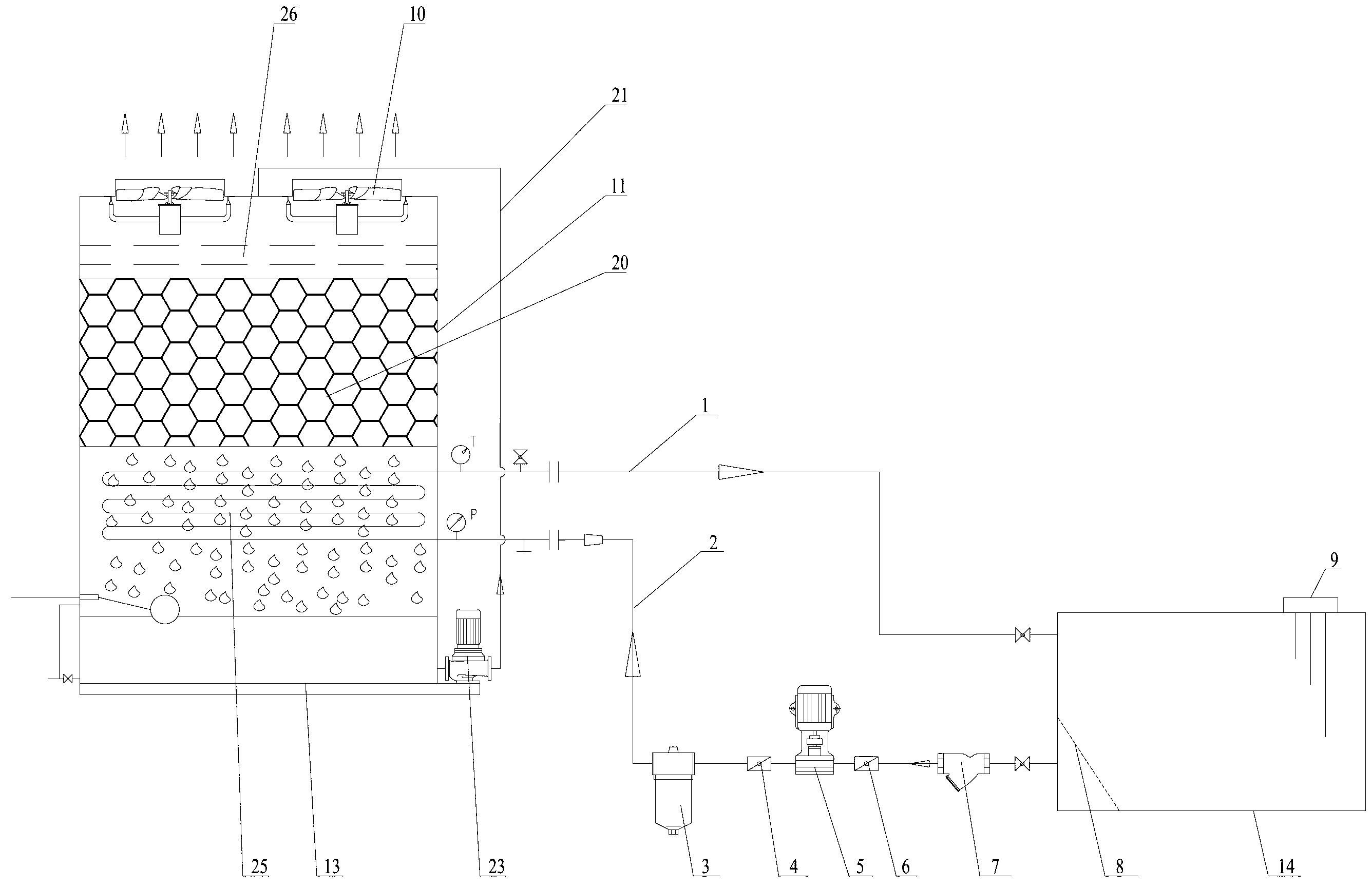
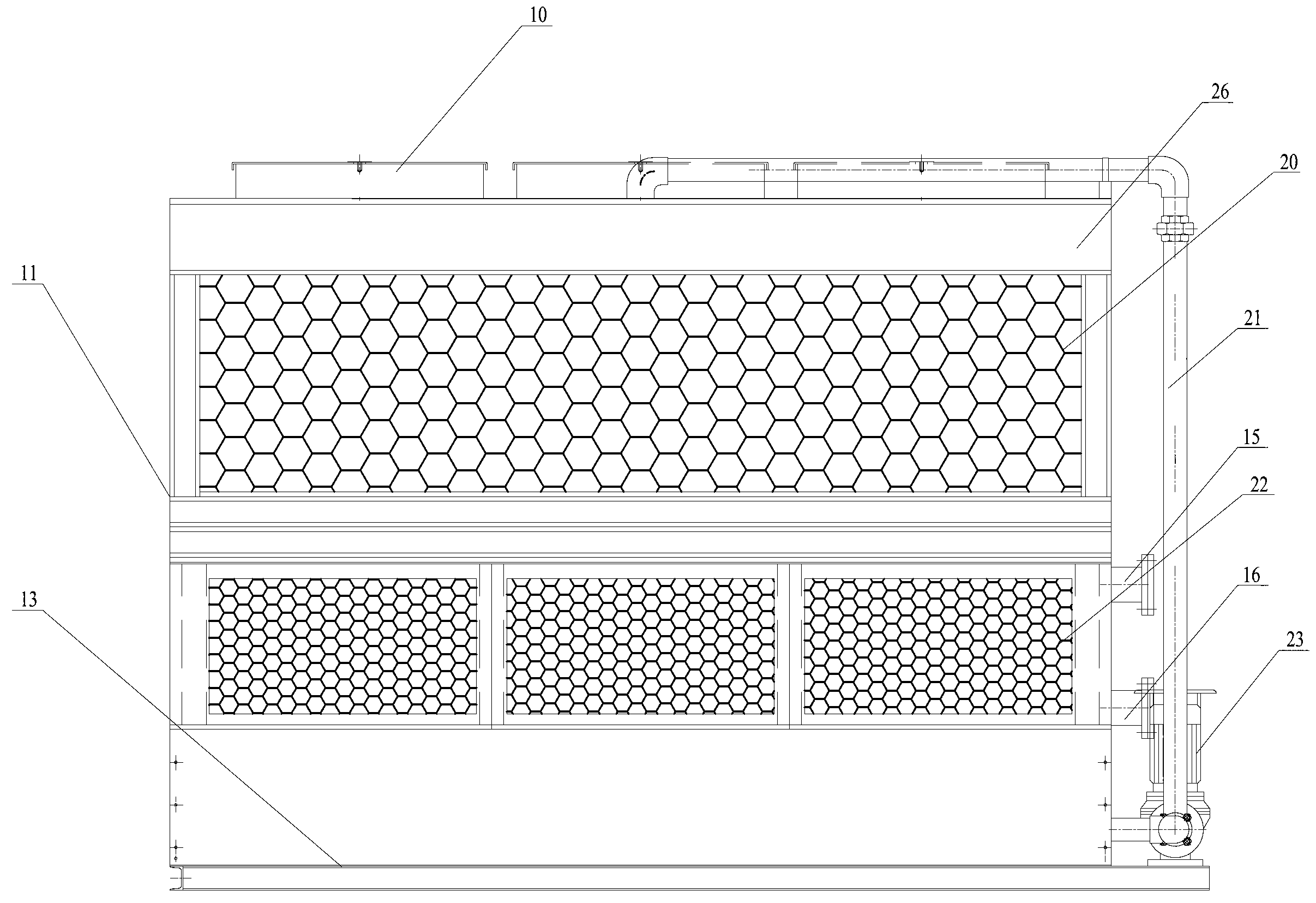
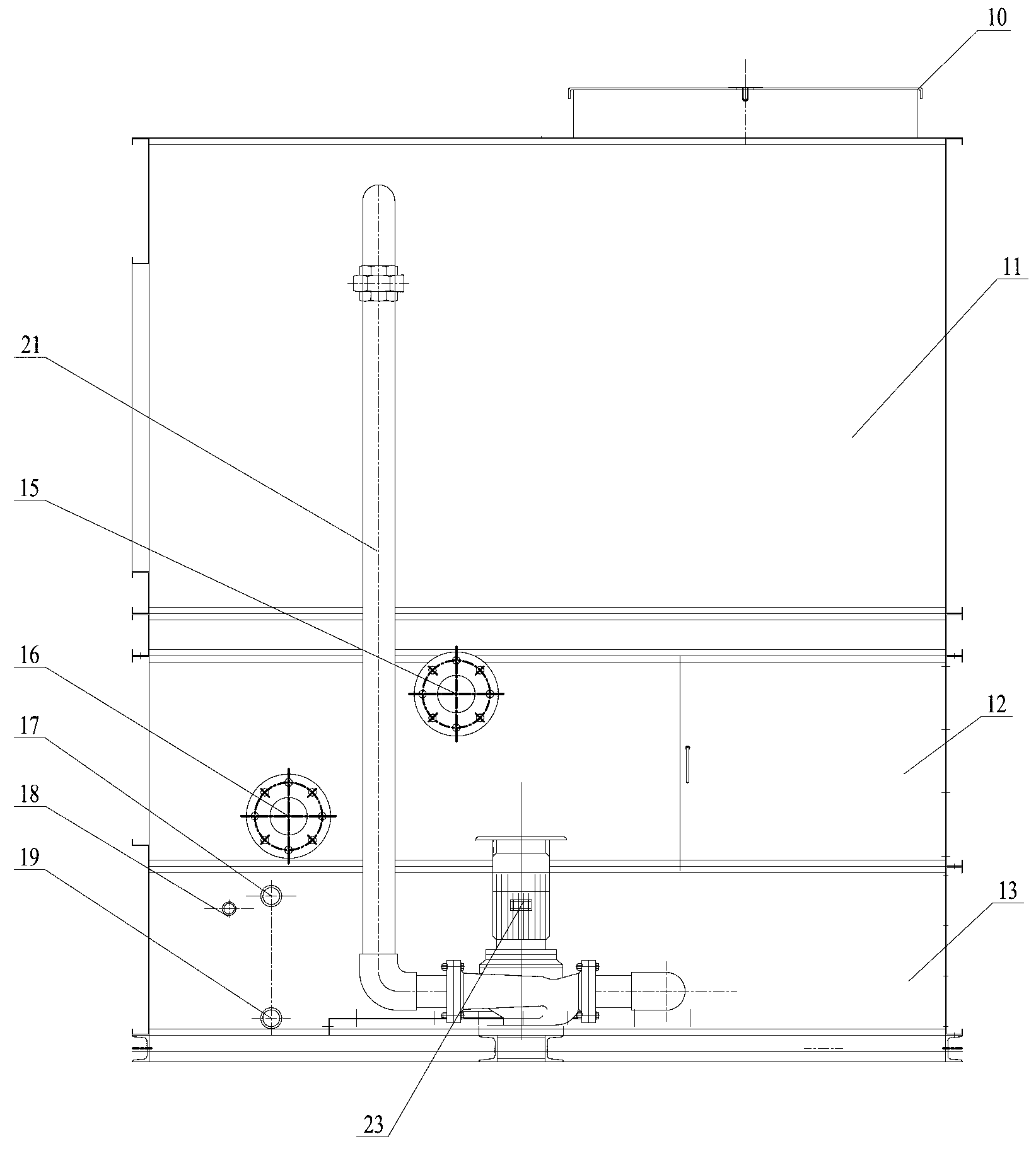
[0026] The closed cooling tower cooling device used in the forging industry includes a closed cooling tower 11 and an oil tank 14, a bracket 24 is fixed in the closed cooling tower, a coil 25 is fixed on the bracket 24, and the closed cooling tower at the position of the coil 25 The cooling tower 11 is provided with an inlet grille 22, one end of the coil pipe 25 has a cold oil outlet 15, and the other end of the coil pipe 25 has a hot oil inlet 16, and a cold oil outlet 15 is connected to the inlet end of the oil tank 14. The oil pipe 1 is connected with the hot oil pipe 2 between the outlet end of the oil tank 14 and the hot oil inlet 16, and a sump 13 is fixed in the closed cooling tower 11 under the coil 25, and a drain valve is arranged at the bottom of the sump 13 19. An overflow valve 17 and a replenishment valve 18 are provided on the sump 13, and a spray packing 20 is...


PUM


Abstract

The invention relates to a closed cooling tower cooling device for forging and stamping industries. A coil is fixed on a support, an air inlet grill is arranged on a closed cooling tower, a cold oil outlet is formed in one end of the coil, a hot oil inlet is formed in the other end of the coil, a cold oil pipe is connected between the cold oil outlet and the inlet end of an oil tank, a hot oil pipe is connected between the outlet end of the oil tank and the hot oil inlet, a water collection tank is fixed in the closed cooling tower, a sewage drainage valve is arranged at the bottom of the water collection tank, an overflow valve and a water replenishing valve are arranged on the water collection tank, spraying fillers are arranged in the closed cooling tower, a bulk water disk is arranged in the closed cooling tower, the inlet end of the bulk water disk is connected with a spraying pipe, a spraying pump is arranged on the spraying pipe, and a fan is positioned at the top end of the closed cooling tower. Work oil of the closed cooling tower cooling device is cooled in a closed cycle mode, oil and water are separated, and oil leakage and oil-water streaming are avoided. The closed cooling tower cooling device improves production efficiency, saves water and reduces power consumption.

Description

technical field [0001] The invention relates to a cooling device for the forging industry, in particular to a closed cooling tower cooling device for the forging industry. Background technique [0002] At present, the temperature of the working oil used in domestic hydraulic machines and hydraulic hammers (electro-hydraulic hammers) will rise to above 50°C after several cycles, which will seriously affect the sealing performance of the equipment and make the forging equipment unable to operate, and the seals will quickly Damage, frequent replacement of seals, affecting production, in order to cool the working oil, in order to cool the working oil, the plate heat exchanger was originally used for indirect cooling with tap water, river water or groundwater. This original cooling method is difficult to achieve the ideal cooling effect, and After long-term use, the cooling fins of the heat exchanger are easily oxidized by high-temperature oil, resulting in oil leakage and oil-wa...

Claims


Application Information

Patent Timeline
Patent Type & Authority Applications(China)
IPC IPC(8): F28D3/02
Inventor 闵颖
Owner WUXI KEJU MACHINERY MFG
Learn More