Compressor, cascade compression system, refrigeration equipment and heating equipment

A compression system and compressor technology, applied in the field of compressors, can solve the problems of complex structure and high cost of the cascade compression system, and achieve the effects of reducing the number of compressors, simplifying the structure, and simplifying the structure of the cascade compression system

Pending Publication Date: 2021-01-12
GREE ELECTRIC APPLIANCES INC
View PDF0 Cites 0 Cited by
  • Summary
  • Abstract
  • Description
  • Claims
  • Application Information

AI Technical Summary

Problems solved by technology

[0003] Aiming at the problems of complex structure and high cost of the existing cascade compression system, the present invention proposes a compressor, cascade compression system, heating equipment and refrigeration equipment, the compressor, cascade compression system, heating equipment and refrigeration equipment The equipment has the technical effect of being able to support more than two refrigerant circulation systems to work independently, simplify the structure of the cascade compression system, and reduce the cost of the cascade compression system

Method used


Image

  • Compressor, cascade compression system, refrigeration equipment and heating equipment
  • Compressor, cascade compression system, refrigeration equipment and heating equipment

Examples


Embodiment Construction

[0035] In order to make the above objects, features and advantages of the present invention more comprehensible, specific implementations of the present invention will be described in detail below in conjunction with the accompanying drawings. In the following description, numerous specific details are set forth in order to provide a thorough understanding of the present invention. However, the present invention can be implemented in many other ways different from those described here, and those skilled in the art can make similar improvements without departing from the connotation of the present invention, so the present invention is not limited by the specific embodiments disclosed below.

[0036] In describing the present invention, it should be understood that the terms "center", "longitudinal", "transverse", "length", "width", "thickness", "upper", "lower", "front", " Back", "Left", "Right", "Vertical", "Horizontal", "Top", "Bottom", "Inner", "Outer", "Clockwise", "Counte...


PUM


Abstract

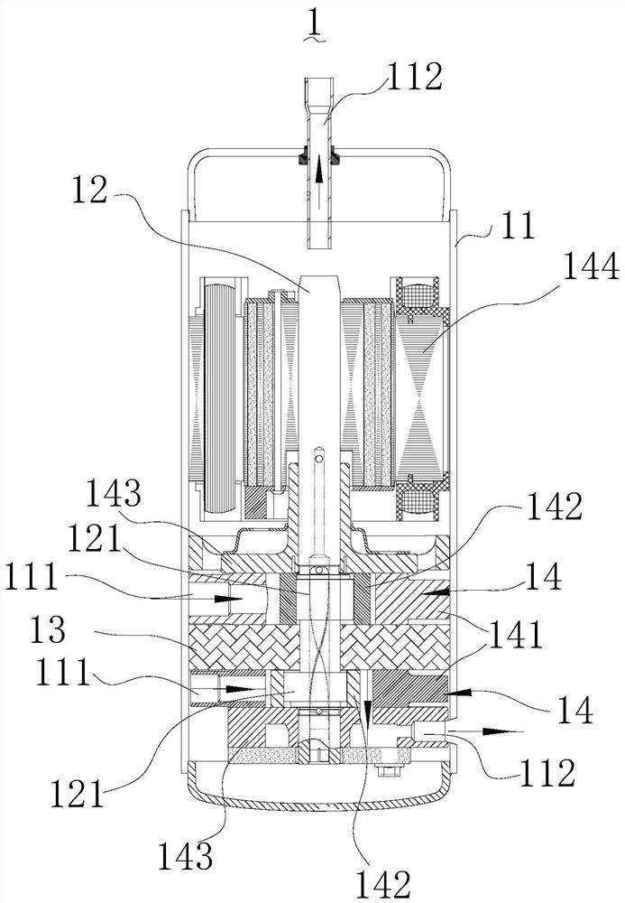
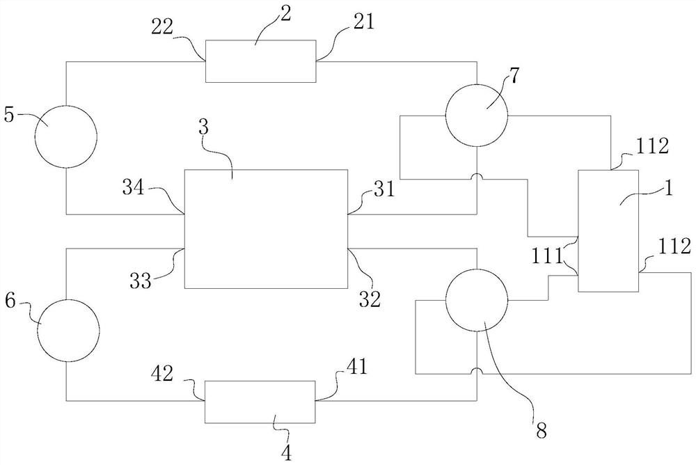
The invention relates to a compressor, a cascade compression system, refrigeration equipment and heating equipment. The compressor comprises a machine shell, a rotating shaft, at least one partition plate and at least two pump body assemblies. The machine shell is provided with a containing cavity, at least two air suction holes and at least two exhaust holes, wherein the air suction holes and theexhaust holes communicate with the containing cavity; the rotating shaft is rotatably arranged in the containing cavity; the at least one partition plate is arranged in the containing cavity, each partition plate sleeves the rotating shaft, the at least one partition plate divides the containing cavity into at least two sub-cavities which are independent of each other, and each sub-cavity is correspondingly communicated with one air suction hole and one exhaust hole; and each pump body assembly is correspondingly connected to the rotating shaft in the corresponding sub-cavity in a matched manner, and each pump body assembly is constructed to be driven by the rotating shaft to suck in refrigerants through the air suction hole of the corresponding sub-cavity where the pump body assembly islocated, compress the refrigerants and then exhaust the refrigerants through the exhaust hole of the corresponding sub-cavity where the pump body assembly is located. Compared with the prior art, simultaneous and independent compression of the multiple refrigerants can be achieved through one rotating shaft, the system structure is simplified, and the system cost is reduced.

Description

technical field [0001] The invention relates to the technical field of compressors, in particular to a compressor, a cascade compression system, refrigeration equipment and heating equipment. Background technique [0002] Cascade compression technology uses two compressors to support two sets of refrigerant circulation systems respectively to achieve an ultra-high pressure ratio, which can be used to solve the technical problem of large-span applications with an ambient temperature of -35°C to 24°C and an outlet water temperature of 80°C. However, in the existing cascade compression system, the structure of the entire system is complicated due to the use of two compressors, and the cost of the system is greatly increased. Contents of the invention [0003] Aiming at the problems of complex structure and high cost of the existing cascade compression system, the present invention proposes a compressor, cascade compression system, heating equipment and refrigeration equipment...

Claims


Application Information

Patent Timeline
Patent Type & Authority Applications(China)
IPC IPC(8): F04C23/00F04C23/02F04C29/12F04C29/00F25B7/00
CPCF04C23/001F04C23/02F04C29/00F04C29/12F04C2240/10F04C2240/30F04C2240/601F25B7/00
Inventor 王传华吕丹丹刘金喜屈清杲
Owner GREE ELECTRIC APPLIANCES INC
Why Eureka
Try Eureka