Automatic design method of numerical control machining tool positioner of complex parts of airplane

A technology of automatic design and tooling design, applied in computer control, instruments, simulators, etc., can solve problems such as inaccurate positioning relationships, complex structure of locators, and errors in data preparation and calculation

Inactive Publication Date: 2010-06-30
SHENYANG AIRCRAFT CORP +1
0 Cites 7 Cited by

AI-Extracted Technical Summary

Problems solved by technology

Due to the complex structure and various forms of the locator, the whole design process is cumbersome, and there are human calculation errors in the data preparation, resulting in the ...

Abstract

The invention discloses an automatic design method of a numerical control machining tool positioner of complex parts of an airplane, which comprises the steps of: automatically designing a work piece, automatically selecting a slandered positioner and automatically modeling positioner parameter. The method can be used for developing an automatic selection procedure of the slandered positioner for a 'tool quick generation subsystem' in a 'quick numerical control machining preparation system of complex parts of airplane (PrtRMP)'. The module can be applied to designing the numerical control machining tool of the complex parts of various type airplanes, improves the designing efficiency of the tool, shortens a tool-developing period and even a whole tool-producing and preparing period, and obtains good application benefit. The method can simplify the designing process of the positioner, realizes the automatic and quick design of the positioner, and improves the designing efficiency and the designing quality of the tool, thereby shortening the assembling and developing period of the airplane.

Application Domain

Programme controlComputer control +1

Technology Topic

AirplaneManufacturing engineering +4

Image

  • Automatic design method of numerical control machining tool positioner of complex parts of airplane
  • Automatic design method of numerical control machining tool positioner of complex parts of airplane
  • Automatic design method of numerical control machining tool positioner of complex parts of airplane

Examples

  • Experimental program(1)

Example Embodiment

[0079] The embodiments of the present invention will be described in detail below with reference to the accompanying drawings. This embodiment is implemented on the premise of the technical solution of the invention. Detailed implementation modes and specific implementation processes are given, but the protection scope of the present invention is not limited to The following implementation examples.
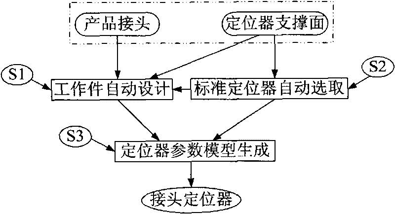
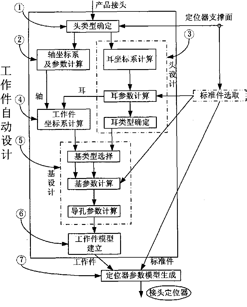
[0080] figure 1 Shown is the automatic design process of the positioner, figure 2 Shown is the flow chart of the automatic design and implementation of the positioner; the automatic design method of the numerical control machining tooling positioner of the aircraft complex component of the present invention is mainly composed of the automatic design of the work piece, the automatic selection of the standard positioner, and the generation of the positioner parameter model.
[0081] The specific implementation steps are as follows:
[0082] Step 1) Automatic design of work piece (S1)
[0083] Workpiece automatic design process see figure 2 , See the structure of positioner and work piece image 3. Specify the joints to be fixed in the product assembly, and then specify the plane used to support the locator on the skeleton, and the system automatically completes the process of head design, base design, and work piece model establishment to generate a three-dimensional work piece model.
[0084] Step 1: Determine the head type
[0085] Figure 4 As the basis for head type reasoning, the corresponding rules are:
[0086] Let y j And n s They are the axis direction of the positioning hole and the normal vector of the support surface of the locator, and both are unit vectors. These two parameters are both spatial parameters and constitute the head type reasoning basis X, which is X=(y j , N s ).
[0087] Rule 1: If|y j ·N s | j ·N s |-1|
[0088] Rule 2: Suppose the head is composed of one or more non-"cylindrical" ears, and the number of them is m. If the number of faces to be supported and positioned on the product joint is n, then m=n.
[0089] If its ε is the zero-domain scale, the head is a "cylindrical" ear; otherwise, that is, the head is composed of one or more non-"cylindrical" ears.
[0090] Step 2: Axis coordinate system and parameter calculation
[0091] The spatial orientation of each unit, including ears, heads, bases, working parts, standard parts, and locators, is uniformly defined and represented by a local coordinate system.
[0092] Step 3: Head design
[0093] Figure 5 Define ear types and their parameterization; specific steps include:
[0094] (1) Ear coordinate system calculation
[0095] Based on a unified local coordinate system.
[0096] (2) Ear parameter calculation
[0097] The parameters of the ear are defined as (d e , B e , T e , L e1 , L e , L e2 , L b1 ), the calculation formula is:
[0098] d e = d j b e = D s t e = e e 1 ( d e ) l e 1 = e e 1 ( b e ) l e = l e 1 + b 2 / 2 l e 2 = e e 3 ( l e ) b e 1 = | P j 1 P j 2 |
[0099] Remarks:
[0100] d j Is the diameter of the positioning hole on the product or process joint, D s Is the diameter of the standard positioner screw or rack, e e1 (d e ), e e2 (b e ) And e e3 (l e ) Are the empirical formulas for calculating the thickness and length of the ear and the distance between the holes, p j1 And p j2 It is the position of the two positioning holes on the product or process joint.
[0101] (3) Determination of ear type
[0102] Determine the ear type based on the following rules
[0103] Rule 1: If n=1, the ear is arc-shaped; otherwise, n=2, the ear is square or fan-shaped.
[0104] Rule 2: If n=2 and, where b e , B e1 , L e1 See ear type and parameterized definition, it is fan shape, otherwise, ear is square shape.
[0105] Where n is the number of positioning holes on the product or process joint.
[0106] Step 4: Workpiece coordinate system calculation
[0107] Workpiece coordinate system calculation is based on a unified local coordinate system.
[0108] Step 5: Design of the substrate
[0109] Image 6 For the base type and its parameterized definition. The specific design steps are divided into:
[0110] (1) Matrix type selection
[0111] According to the following rules to present the base type: if n e = 1, the matrix is ​​cylindrical; otherwise, the matrix is ​​block. Where n e Is the number of ears
[0112] (2) Calculation of matrix parameters
[0113] d b = b e d b 1 = D s l b 1 = l s + e b 1 l b = e b 2 ( l b 1 ) w b = d jj d b 2 = l s 1 + e b 3 w b 1 = d ss
[0114] Remarks:
[0115] B e And t e see Figure 5 , L s And d s Is the diameter and length of the screw connection head in the standard positioner, e b1 , E b2 (l b1 ) And e b3 Is the length allowance and calculation experience, d jj Is the distance between the two positioning surfaces on the product or process joint, d ss Is the distance between the two guide rods on the standard positioner;
[0116] (3) Calculation of pilot hole parameters
[0117] Step 6: Build the work piece model
[0118] Combine the head and the base to form a single solid model.
[0119] Step 2) Automatic selection of standard part locator (S2)
[0120] This program needs to be called when the work piece is designed, and at the same time, the qualified standard locator is determined and called.
[0121] Figure 7 Shown is the automatic selection process of the standard locator, including: standard locator locating area calculation, product joint position calculation, candidate locator selection, locator optimization, etc. The specific implementation steps are as follows:
[0122] Step 1) Calculate the localizable domain of the standard locator (B1)
[0123] Figure 8 Shown is the location of the connector locator. Can be expressed as B t [x 1 , Y 1 , L 1 , W 1 ], where (x 1 , Y 1 ) Is the product connector in the definition system O l X l Y l Position in, (l 1 , W 1 ) Is the positionable domain along X l And Y l The size of the direction;
[0124] Step 1: Determine the working surface of the locator manually according to the product joint, position and direction, and related conditions of the supporting element;
[0125] Step 2: Use the working surface to calculate the cross-section and cross-sectional dimensions (a, b) of the support element. The calculation method is: (The following takes the standard guide rod positioner HB595 as an example to illustrate. This type of positioner is divided into two specifications according to the guide rod telescopic length L value of 300 and 500, which are expressed as: 300HB595 and 500HB596. The positioner See the positioning domain Figure 8 Shown. )
[0126] Calculate the localizable domain: The localizable domain of HB595 is: B HB595 [x 1 , Y 1 , L 1 , W 1 ]=A HB595 (L, (a, b)), where A HB595 It is the positionable calculation operator of HB595, which is:
[0127] x l = 100 + a / 2 y l = 115 - ( b - 130 ) / 2 l l = 0 w l = L + ( b - 130 )
[0128] In the formula, the meaning of L is as mentioned above; (a, b) are the interface dimensions of the supporting element.
[0129] Determine the parameter space of the positioner: the parameter space L of HB595 is: L HB595 ={(L), {(300), (500)}}
[0130] Calculate location domain: HB595 location domain D HB595 Expressed as:
[0131] D HB595 [x sl , Y sl , L sl , W sl ]=C HB595 ((a, b))
[0132] x sl = a / 2 y sl = - ( b - 130 ) / 2 l sl = 0 w sl = b - 130
[0133] Step 3: Calculate the single domain of all specifications of locators in each type according to the cross-sectional size of the supporting element. The single domain of HB595 is: B HB595 [x1, y1, l1, w1]=A HB595 (300, (a, b))
[0134] According to the calculation of the previous steps (1)-(3) and the external data definition of standard positioning, the external data of HB595 can be defined as follows:
[0135] {TYPE: HB595
[0136] SIZE: A300, A500, B300, B500
[0137] PARAMETERS: L
[0138] VALUES: 300, 500, 300, 500
[0139] LOCATION: 100+a/2, 115-(b-130)/2, 0, L+(b-130)
[0140] POSITION: a/2, -(b-130)/2, 0, b-130
[0141] }
[0142] Step 4: Calculate the position and coordinate axis direction of the positioning domain definition system in the tooling design coordinate system according to the setting of the support element section position and the positionable domain definition system. Among them, the definition system is the rectangular coordinate system O l X l Y l , Where, the origin O l Generally take the centroid of the cross section of the support element in the working surface, X l The axis is parallel to the normal direction of the support surface of the positioner, Y l The axis points in the direction of the product connector (see Figure 8 ).
[0143] Step 2) Product joint position calculation (B2)
[0144] Picture 9 Coordinate transformation is used for calculation of product joint position. The calculation process of the product joint position is:
[0145] Step 1: Calculate the position of the product joint in the tooling design system according to the position of the complex component design coordinate system in the tooling design space;
[0146] Step 2: According to the position of the product joint in the tooling space, calculate its position coordinate in the localizable domain definition system. which is:
[0147] Known conditions are the design coordinate system of complex components O d X d Y d Z d And localizable domain definition system O l X l Y l Z l In the tooling design coordinate system O f X f Y f Z f In the position and direction, and the product connector in the O d X d Y d Z d Position in P(x d , Y d ,z d ). According to calculations, P is in O l X l Y l Z l Position (x l j , Y l j ,z l j )for:
[0148] x l j = O l P → · X l → y l j = O l P → · Y l → z l j = O l P → · Z l →
[0149] Step 3) Candidate locator selection (B3)
[0150] According to the given candidate locator candidate conditions, determine the locator that meets the conditions from the standard parts library. The selection basis is:
[0151] For a standard locator, t is the type, s is the specification, and B t [x l , Y l , L l , W l ]
[0152] Define the single domain in the system for the positionable domain, if the product connector position (x l j , Y l j ) Satisfies the following formula,
[0153] Then the locator is an optional locator.
[0154] x l ≤ x l j ≤ x l + l l y l ≤ y l j ≤ y l + w l
[0155] Step 4) Locator optimization (B4)
[0156] If the locator is not unique, you need to select the locator with the highest priority based on the principle of preference. The principle of locator optimization is as follows:
[0157] (1) The principle of shape matching, that is, if the basic shape of the working head is block, the double-lead standard positioner is preferred; otherwise, that is, the basic shape of the working head is a cylinder, and the single-lead positioner is selected.
[0158] (2) The principle of minimum specification. If there are multiple applicable specifications in the same type of positioner at the same time, the smallest specification among them shall be selected first.
[0159] After the above steps, by manually selecting the product joint and the support surface of the locator as initial conditions, the standard locator meeting the positioning conditions can be automatically selected.
[0160] Step 3) Locator parameter model generation (S3)
[0161] Establish the assembly relationship between the work piece and the standard positioner, and generate a complete parametric model of the positioner.
[0162] Among them, the locator designed by the CAD software developed by applying the above method steps of this embodiment is such as Picture 10 As shown, 20 is the working head, 21 is the standard guide rod positioner, which is automatically selected.

PUM

no PUM

Description & Claims & Application Information

We can also present the details of the Description, Claims and Application information to help users get a comprehensive understanding of the technical details of the patent, such as background art, summary of invention, brief description of drawings, description of embodiments, and other original content. On the other hand, users can also determine the specific scope of protection of the technology through the list of claims; as well as understand the changes in the life cycle of the technology with the presentation of the patent timeline. Login to view more.
Why Eureka
Try Eureka