Light-emitting diode light source driving circuit and method for automatically compensating luminance thereof

A light source driving circuit and light-emitting diode technology, applied in the direction of light source, electric light source, lamp circuit layout, etc., can solve the problems of LED light source brightness change, inconvenient use, affecting the operation stability of the driving circuit 120, etc., so as to avoid the change of brightness Effect

Inactive Publication Date: 2013-08-28
NOVATEK MICROELECTRONICS CORP
View PDF5 Cites 0 Cited by
  • Summary
  • Abstract
  • Description
  • Claims
  • Application Information

AI Technical Summary

Problems solved by technology

[0004] (1) The size of the voltage ripple of the direct current voltage VDC will make the start time and stop time of the driving circuit 120 have periodic operation, thereby affecting the operation stability of the driving circuit 120;
[0005] (2) The magnitude of the voltage ripple of the DC voltage VDC will affect the LED light source 130 connected to the output terminal of the drive circuit 120, and this voltage ripple will cause the average current or average voltage of the LED light source 130 to change, and also cause the brightness of the LED light source to change.
[0006] In the driving circuit 120 of the known technology, since the direct current voltage VDC contains the influence of the ripple voltage, the average current or voltage flowing through the LED light source 130 cannot be stably controlled; that is, the luminance of the LED light source 130 will vary. Phenomenon, thus causing inconvenience in use

Method used


Image

  • Light-emitting diode light source driving circuit and method for automatically compensating luminance thereof
  • Light-emitting diode light source driving circuit and method for automatically compensating luminance thereof
  • Light-emitting diode light source driving circuit and method for automatically compensating luminance thereof

Examples


Embodiment Construction

[0064] The ensuing description of the invention generally refers to specific structural embodiments and methods. It is to be understood that there is no intention to limit the invention to the specific disclosed embodiments and methods, but that the invention can be practiced using other features, elements, methods and embodiments. The preferred embodiments are described to illustrate the invention, not to limit its scope, which is defined by the claims. Those skilled in the art will recognize various equivalents of the subsequent description. Similar elements in various embodiments are collectively denoted by similar reference numerals.

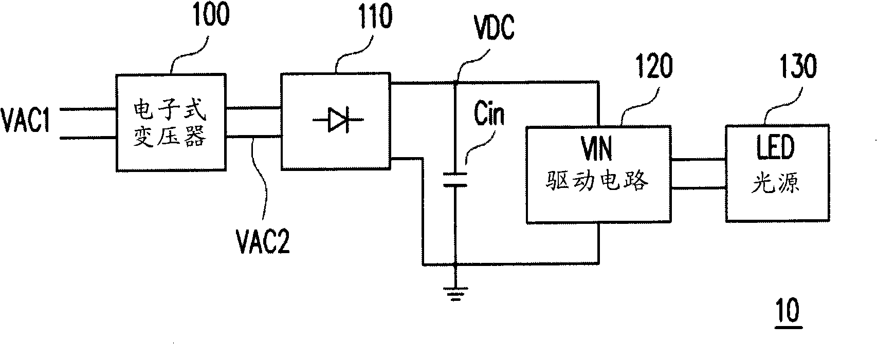
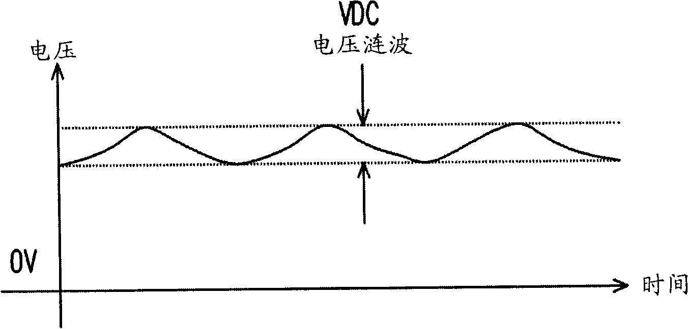
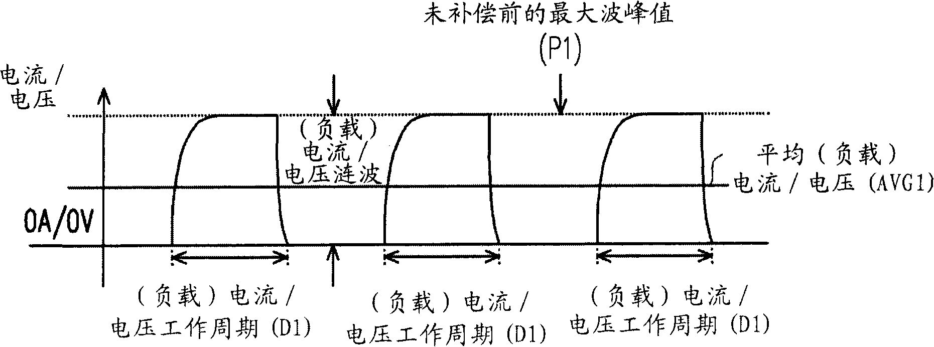
[0065] image 3 and Figure 4 Waveforms of (load) current or voltage before compensation are shown. Please refer to image 3 and Figure 4 . Because the input capacitor Cin will affect the direct current voltage VDC, the direct current voltage VDC contains a ripple component and causes voltage ripple to change, thereby causing the ave...


PUM


Abstract

The invention discloses a light-emitting diode light source driving circuit and a method for automatically compensating luminance. The method comprises the following steps of: providing a target value, detecting a work period of a pulse outputted by the LED light source driving circuit, wherein the pulse is used for driving the LED light source to illuminate, determining a crest value according to the target value and the work period, and setting a crest level of the pulse according to the crest value. The light source driving circuit and the method for automatically compensating luminance thereof can provide a stable average current / voltage to the LED light source so as to avoid the change of the light source luminance.

Description

technical field [0001] The invention relates to a light source adjustment technology, and in particular to a light emitting diode (LED) light source driving circuit and its automatic brightness compensation method. Background technique [0002] figure 1 A block diagram of a conventional LED light source device is shown. Please refer to figure 1 , the LED light source device 10 includes an electronic transformer 100 , a rectifier circuit 110 , an input capacitor Cin, a driving circuit 120 , and an LED light source 130 . Firstly, the output of the traditional AC-to-AC electronic transformer 100 is an AC voltage VAC2 with high frequency. For example, a low-frequency AC voltage VAC1 of 60 Hz (Hz) is used, and the AC voltage VAC1 is converted by an electronic transformer 100 into a high-frequency AC voltage VAC2 of 25 kHz to 100 kHz (KHz), wherein the AC voltage VAC1, The effective value voltage (Vrms) of VAC2 is respectively 110 volts (Volt) and 12 volts (Volt). Next, the A...

Claims


Application Information

Patent Timeline
Patent Type & Authority Patents(China)
IPC IPC(8): H05B37/02
CPCY02B20/42Y02B20/40
Inventor 刘翼德谢致远颜志仁
Owner NOVATEK MICROELECTRONICS CORP
Why Eureka
Try Eureka