Supercharge Your Innovation With Domain-Expert AI Agents!

Liquid tank with vent-to-atmosphere mechanism

A technology of liquid containers and liquid nozzles, which is applied in printing, thin material handling, transportation and packaging, etc. It can solve the problems that it is impossible to remove dust and impurities, and achieve the effect of ensuring effectiveness and stability

Inactive Publication Date: 2010-06-30
RICOH KK
View PDF4 Cites 0 Cited by
  • Summary
  • Abstract
  • Description
  • Claims
  • Application Information

AI Technical Summary

Problems solved by technology

Since the filter is not placed on the same side of the valve as the atmosphere, it is impossible to remove dust and impurities attached to the valve plug and seat

Method used


Image

  • Liquid tank with vent-to-atmosphere mechanism
  • Liquid tank with vent-to-atmosphere mechanism
  • Liquid tank with vent-to-atmosphere mechanism

Examples


Embodiment Construction

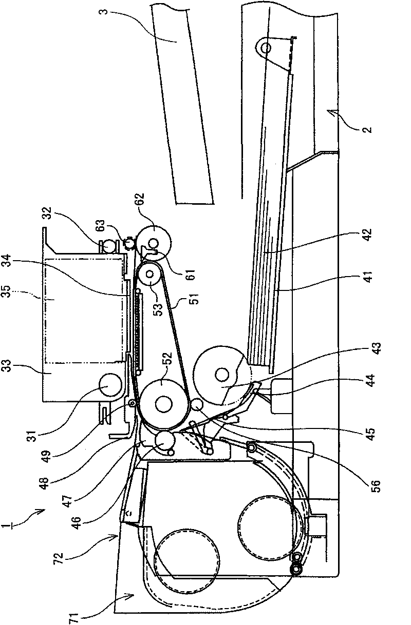
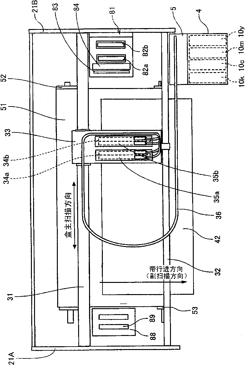
[0037] Hereinafter, various embodiments of the present invention will be described with reference to the drawings. will refer to figure 1 with figure 2One example of the image forming apparatus according to the present invention is explained. figure 1 is a side view showing the overall configuration of the image forming apparatus. figure 2 is a plan view showing main parts of the image forming apparatus.

[0038] This image apparatus is a serial-type image forming apparatus having a main guide bar 31 and an auxiliary guide bar 32 serving as guide members which are placed horizontally on the left and right side plates 21A and 21B of the apparatus 1 between. Guide bars 31 and 32 convey a cassette 33 movable in the main scanning direction. The main scanning motor (not shown) passes through the timing belt (timingbelt) in the figure 2 The cartridge 33 is driven in the main cartridge scanning direction indicated by the middle arrow.

[0039] The cartridge 33 has print hea...


PUM


Abstract

A liquid tank includes a vent-to-atmosphere mechanism configured to open and close a vent-to-atmosphere passageway for venting an internal reservoir space connected to a liquid spray head to atmosphere, the vent-to-atmosphere mechanism including a cylindrical member, a valve seat disposed inside the cylindrical member, a valve plug disposed inside cylindrical member and movable to come in contact with or separate from the valve seat, a movable member disposed inside the cylindrical member on an atmosphere side of the valve plug in a slidable manner to cause a movement of the valve plug, the movable member having an outer surface in movable contact with an inner surface of the cylindrical member and having a communication passageway formed therethrough for communication with atmosphere, and a filter member disposed at the communication passageway to capture foreign material.

Description

technical field [0001] The present application generally relates to a liquid tank and an image forming apparatus, and more particularly, to an image forming apparatus equipped with a printhead for ejecting liquid droplets and a liquid tank used in such an image forming apparatus. Background technique [0002] Some image forming apparatuses such as printers, facsimile machines, copiers, plotters, and multifunction machines may use a print head including a mechanism for ejecting liquid onto paper while moving the position of paper used as a medium. A liquid jet that drops to form an image. The term "media" may hereinafter be referred to as "paper", but is not meant to limit the type of material used. Other terms such as "recorded medium", "recording medium", "transfer member", "recording paper" may also be used to refer to the same thing as the term "medium". For the same reason, terms such as "recording" and "printing" mean the same as "image forming". [0003] In this dis...

Claims


Application Information

Patent Timeline
Patent Type & Authority Applications(China)
IPC IPC(8): B41J2/175
CPCB41J2/17513B41J2/17563B41J2/17553B41J2/1752B41J2/17509B41J2/17596Y10T137/86292
Inventor 吉池祐尚
Owner RICOH KK
Features
  • R&D
  • Intellectual Property
  • Life Sciences
  • Materials
  • Tech Scout
  • Unparalleled Data Quality
  • Higher Quality Content
  • 60% Fewer Hallucinations
Learn More