Force touch sensation feedback and force intensity control method of mechanical artificial hand based on myoelectric control

A technology of myoelectric control and control method, applied in the direction of prosthesis, medical science, etc., can solve the problems that the disabled cannot take fragile daily necessities, it is difficult to adapt to normal life, and the prosthetic hand cannot control the clamping force, etc. , to achieve the effect of avoiding damage to items, returning to normal life, and taking items quickly and flexibly

Active Publication Date: 2010-07-07
SOUTHEAST UNIV
View PDF0 Cites 43 Cited by
  • Summary
  • Abstract
  • Description
  • Claims
  • Application Information

AI Technical Summary

Problems solved by technology

[0002] Although the myoelectric control prosthetic hand has appeared for many years, how to solve the control problem of the clamping force of the mechanical prosthetic hand has always been an important content of the manipulator control. The size may not be able to realize the convenient strength control method adapted to the disabled, so that the disabled cannot take daily necessities such as fragile and deformable, or it is necessary to use more complicated equipment or methods to realize this function. Difficulty adjusting to normal life after electroprosthetic hand

Method used


Image

  • Force touch sensation feedback and force intensity control method of mechanical artificial hand based on myoelectric control
  • Force touch sensation feedback and force intensity control method of mechanical artificial hand based on myoelectric control
  • Force touch sensation feedback and force intensity control method of mechanical artificial hand based on myoelectric control

Examples


Embodiment Construction

[0014] The present invention will be further described below in conjunction with accompanying drawing and specific embodiment

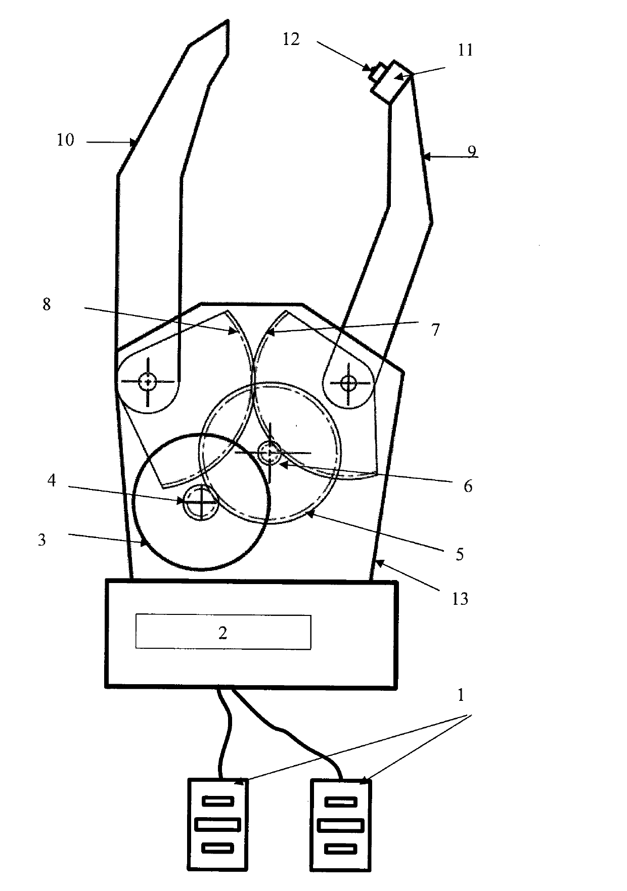
[0015] Such as figure 1 As shown (only the mechanical prosthetic hand draws two fingers for clamping in the figure), two myoelectric signal acquisition electrodes 1 are connected to the myoelectric prosthetic hand control module 2 at the root of the prosthetic hand, and the motor drive of the myoelectric prosthetic hand control module 2 The signal line is connected to the micro-DC motor 3 on the mechanical prosthetic hand 13, and the motor gear 4 installed on the output shaft of the micro-DC motor 3 is meshed with the large gear 5 for transmission, and the transmission ratio is 4:1, which plays the role of deceleration and force boosting; 5. The coaxial pinion 6 meshes with the thumb 9 root gear 7. The transmission ratio is 10:1, which also plays the role of deceleration and boosting. The shaft of the thumb 9 root gear 7 is fixedly connected with the ...


PUM


Abstract

The invention provides a force touch sensation feedback and force intensity control method of a mechanical artificial hand based on myoelectric control, which comprises the following steps: installing two myoelectric signal collection electrodes which are pasted on the body surface of a muscle activity region of a disabled arm of the human body; respectively collecting finger opening and closing myoelectric signals which are directly proportional to the muscle tensioning degree; inputting the collected signals into a single chip; carrying out section quantification according to different magnitude values; outputting different section signals; driving a miniature DC motor through a motor driving circuit; outputting section speed values corresponding to the section quantification of the finger clamping force intensity through the rotation of the miniature DC motor via a gear transmission mechanism; and at the same time, installing a force touch sensation sensor at the finger end of a thumb of the artificial hand. When the finger is closed, the force touch sensation sensor is squeezed for outputting force touch sensation signals which are fed back to the single chip to be correspondingly compared to a force intensity section quantification value set by program. The single chip continuously regulates signals output to the motor driving circuit for driving the rotation speed of the miniature DC motor to be correspondingly changed, so the finger opening and closing speed is correspondingly changed until the affiliated section clamping force intensity conforming to the set requirements is reached.

Description

technical field [0001] The invention relates to a prosthetic manipulator designed based on the principle of myoelectric signals, in particular to a method for force-tactile feedback and force control of a mechanical prosthesis based on myoelectric control, and belongs to the technical fields of signal acquisition and processing, computer, motor control, etc. related to manipulators Background technique [0002] Although myoelectrically controlled prosthetic hands have appeared for many years, how to solve the problem of controlling the clamping force of the mechanical prosthetic hand has always been an important content of manipulator control. The existing myoelectric prosthetic hands cannot realize the control of the clamping force of the prosthetic hand. The size may not be able to realize the convenient strength control method adapted to the disabled, so that the disabled cannot take daily necessities such as fragile and easily deformed, or it is necessary to use more comp...

Claims


Application Information

Patent Timeline
IPC IPC(8): A61F2/72
Inventor 宋爱国章华涛崔建伟钱夔包加桐
Owner SOUTHEAST UNIV
Why Eureka
Try Eureka