Gear device

A technology of gear device and gear shaft, which is applied to transmission parts, belts/chains/gears, transportation and packaging, etc. It can solve the problems of cumbersome adjustment operations and achieve the effect of convenient adjustment operations

Inactive Publication Date: 2010-07-07
HITACHI LTD
View PDF1 Cites 4 Cited by
  • Summary
  • Abstract
  • Description
  • Claims
  • Application Information

AI Technical Summary

Problems solved by technology

[0007] As described above, in the gear unit disclosed in Patent Document 1, in order to install the spacer 23 for adjusting the clearance, the bearing cap 22 needs to be installed after many steps, and the adjustment work at the time of assembly is very cumbersome.

Method used


Image

  • Gear device
  • Gear device
  • Gear device

Examples


Embodiment Construction

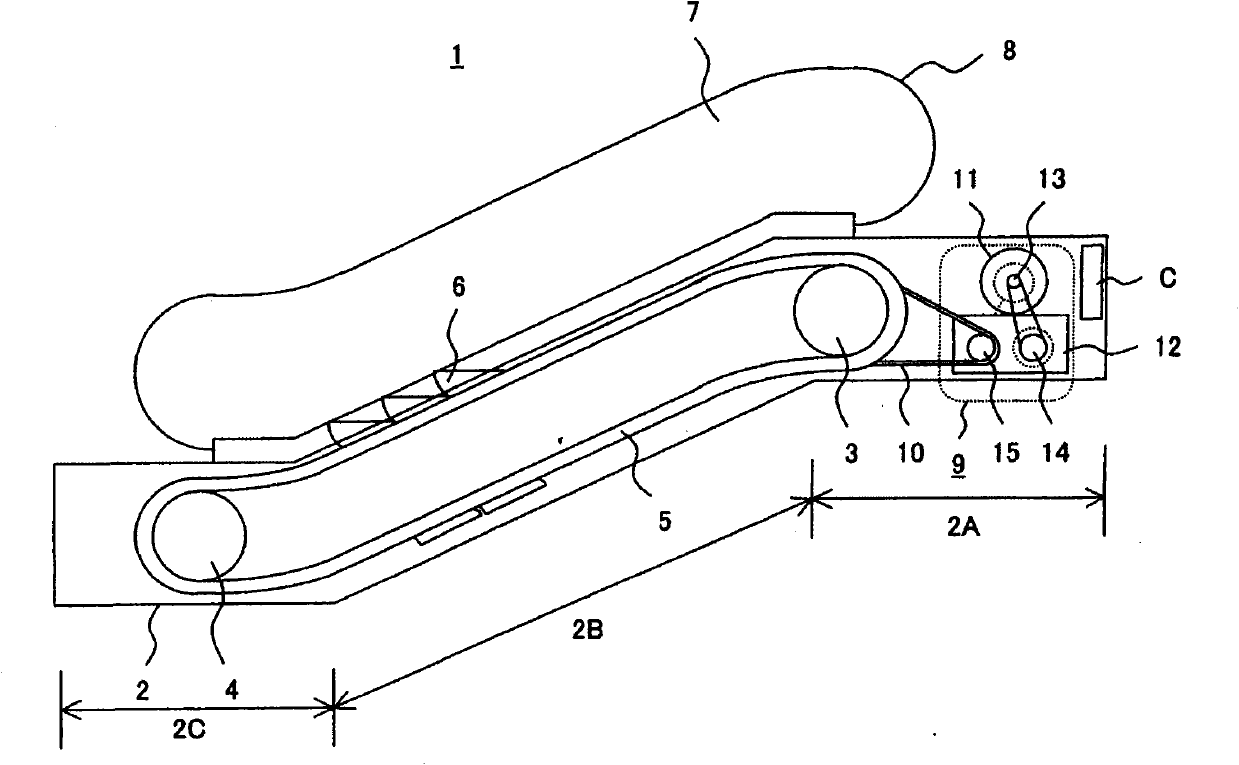
[0045] Refer to the following Figure 1 to Figure 5 The shown gear unit used for the driving device of the escalator is an explanation of one embodiment of the gear unit of the present invention.

[0046] The escalator 1 has: a frame main body 2 composed of an upper horizontal frame 2A, an intermediate inclined frame 2B, and a lower horizontal frame 2C arranged across an upper floor and a lower floor; a drive sprocket 3, which 3 is pivotally supported in the upper horizontal frame 2A; the driven sprocket 4 is pivotally supported in the lower horizontal frame 2C; the endless step chain 5, the endless step chain 5 is wound on the above-mentioned drive sprocket 3 and driven sprocket 4; a plurality of steps 6, which are connected to the above-mentioned step chain 5, and have a pedal that is always kept horizontal on the outgoing side; a railing panel 7, The railing panel 7 is vertically arranged on the position corresponding to both sides of the width direction of the step 6 of t...


PUM


Abstract

The present invention provides a gear device for adjusting operations during convenient assembling without complicated processes. According to the utility model, a reference surface is formed at the external side of the side wall of a gear box for communicating with a bearing holding hole, and a bearing cover is installed at a position outer the reference surface. According to the structure above, whether a height difference exists between a bearing and the reference surface or not can be determined through the touching of fingers or by a ruler, is the height difference is determined to exist, a pad for gap adjusting is positioned at the position of height difference, thereafter, whether the pad for gap adjusting and the reference surface are flushed or not can be determined through the touching of fingers, by a ruler and the like, and when the pad for gap adjusting and the reference surface are determined to be flushed, the bearing cover is installed, therefore, the gapping place between the bearing and the bearing cover can be adjusted simply and conveniently, and operation adjusting in assembling can be performed conveniently.

Description

technical field [0001] The present invention relates to a gear device constituting, for example, a driving device of passenger conveying equipment such as escalators and motorized walkways, and more particularly, to a gear having a structure in which a bearing for pivotally supporting a gear shaft is held on a side wall of a gear box device. Background technique [0002] A gear unit having a structure in which a bearing that pivotally supports a gear shaft is held on a side wall of a gear case, as disclosed in Patent Document 1, for example, is a known technique. Such as Figure 7 As shown, in the gear device disclosed in Patent Document 1, a bearing holding hole 21 is formed on the side wall 16H of the gear box 16, and the bearing 20 that supports the gear shaft 17 so as to be rotatable is inserted and mounted in the bearing holding hole 21. , and the outer side of the bearing holding hole 21 is covered by the bearing cap 22 . The inner side of the bearing cap 22 is forme...

Claims


Application Information

Patent Timeline
Patent Type & Authority Applications(China)
IPC IPC(8): F16H57/00F16C33/78B66B23/00F16C35/077F16H57/02F16H57/021F16H57/022F16H57/023F16H57/031
Inventor 福田敏行竹本启辅山下智典
Owner HITACHI LTD
Why Eureka
Try Eureka