
Device for transferring eggs

A transfer device and transfer technology, applied in packaging, packaging food, packaging eggs, etc., can solve problems such as wasting time

Active Publication Date: 2010-07-07
股份公司南备尔
View PDF1 Cites 16 Cited by
  • Summary
  • Abstract
  • Description
  • Claims
  • Application Information

AI Technical Summary

Problems solved by technology

[0006] Therefore, the time for multiple transfer cups to return to the original position after transferring the eggs to the single conveyor belt becomes a waste of time, and there is room for improvement in high-speed processing.

Method used


Image

  • Device for transferring eggs
  • Device for transferring eggs
  • Device for transferring eggs

Examples


Embodiment approach 1

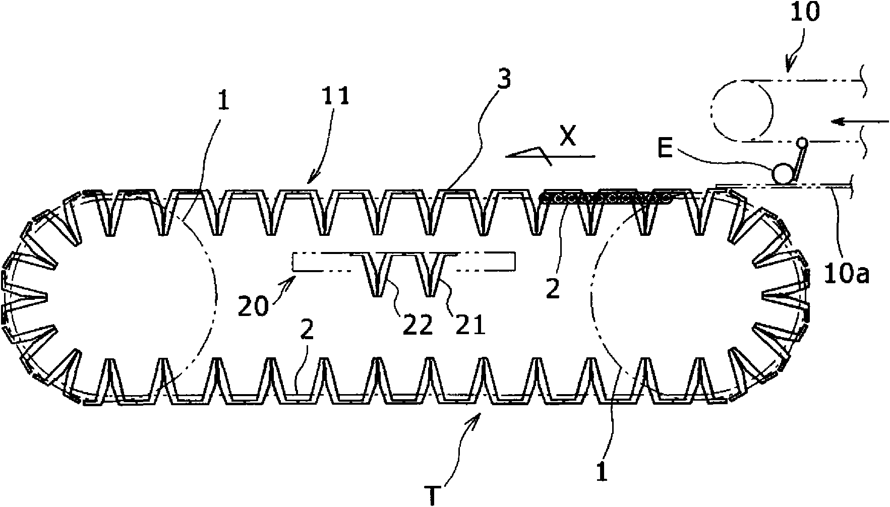
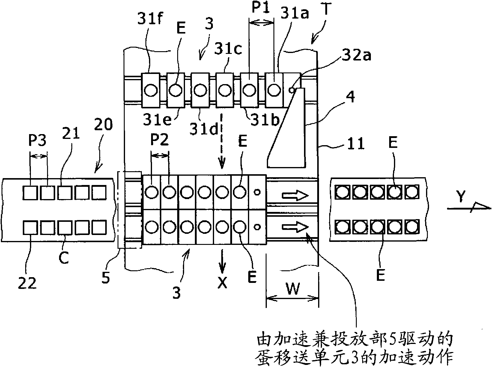
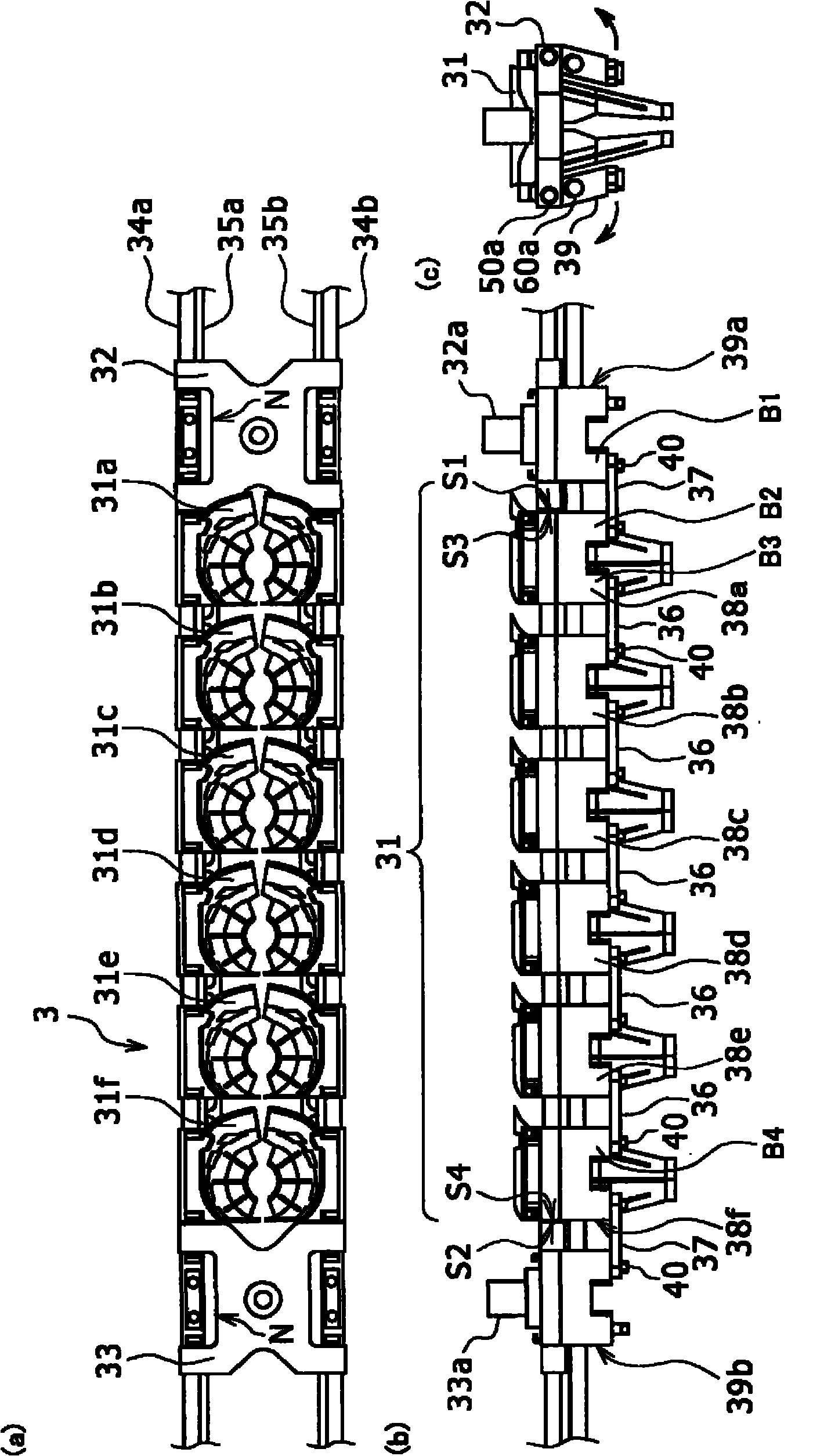
[0034] Next, as Embodiment 1 of this invention, the transfer apparatus T of an egg is demonstrated based on drawing. figure 1 It is a schematic side view of the egg transfer device T of the first embodiment of the present invention, figure 2 is a schematic top view of the egg transfer device T, image 3 It is a concrete structural diagram of the egg transfer unit 3 which is the storage container row of the egg transfer apparatus T. also, Figure 4 is a perspective view of the egg transfer unit 3, Figure 5 It is a partial concrete configuration diagram of the egg transfer unit 3 .

[0035] Such as figure 1 As shown, the egg transfer device T of this embodiment is roughly composed of an endless conveyor belt 11 arranged in the same direction as the conveying direction of the predetermined conveyor belt 10 and an egg along the conveying direction (X direction) intersecting with the endless conveyor belt 11 . The next-stage conveyor belt 20 arranged in the direction (orthog...

Embodiment approach 2

[0076] Next, an egg transfer device T according to Embodiment 2 of the present invention will be described with reference to the drawings. Figure 8 A schematic plan view showing an egg transfer device T according to Embodiment 2 of the present invention, and figure 2 The same parts of the illustrated egg transfer device T are denoted by the same reference numerals, and description thereof will be omitted.

[0077] The basic structure of the egg transfer apparatus T of this embodiment is substantially the same as the egg transfer apparatus T of 1st Embodiment mentioned above. Such as Figure 8 As shown, the egg transfer device T of this embodiment is composed of an endless conveyor belt 11 , an acceleration unit 6 , a delivery unit 7 arranged at a position opposite to the acceleration unit 6 , and a next-stage conveyor belt 20 .

[0078] if compare Figure 8 and figure 2 It can be seen that the egg transfer device T of this embodiment does not have the adjustment plate 4...


PUM


Abstract

A device for transferring eggs comprises a regulation board (4) for limiting the containing seat pitch of an egg transfer unit (3) to a pitch substantially equal to the containing seat pitch in the line direction of a next position conveyor (20) in a process for carrying the egg transfer unit (3) having a predetermined number of containing seats slidable in the carrying width direction respectively, and an accelerating / discharging section (5) for urging the egg transfer unit (3) in the same direction as the carrying direction of the next position conveyor (20) and synchronizing the moving speed of the egg transfer unit (3) in the urging direction substantially with the carrying speed of the next position conveyor (20) when the egg transfer unit (3) having a pitch limited substantially equal to the containing seat pitch in the line direction of a next position conveyor (20) by the regulation board (4) arrives above the next position conveyor (20), and discharging the eggs (E) containedin the egg transfer unit (3) collectively to the containing seats of the next position conveyor (20).

Description

technical field [0001] The present invention relates to an egg transfer device, specifically, it involves accepting eggs transported from the upstream side in a predetermined number of horizontal rows with the long axis direction as the horizontal direction with the long axis direction of the eggs as the vertical direction, and then placing the specified A transfer device for eggs (generally referred to as eggs) that transfers a certain number of eggs to the next-level conveyor belt such as a single-row conveyor belt. Background technique [0002] In the past, Japanese Patent Laid-Open No. 50-97066 (Patent Document 1) discloses such a transfer device: a plurality of transfer cups are used to receive and pass through a predetermined conveyor belt in a predetermined row with the long axis direction as the horizontal direction. After counting the eggs transported in horizontal rows, take the long axis direction of the eggs as the vertical direction, for example, a transfer devi...

Claims


Application Information

Patent Timeline
Patent Type & Authority Applications(China)
IPC IPC(8): B65G47/30B65B35/36B65B35/44
CPCB65B23/06
Inventor 高田雅孝
Owner 股份公司南备尔
Learn More