Tube pile structure

A pipe pile and pile head technology, which is applied in the field of pipe pile structure improvement, can solve the problems of poor prestress, single direction of force, and poor firmness, and achieve the effect of good firmness and strong prestress

Inactive Publication Date: 2010-07-14
浙江大东吴集团建设有限公司
View PDF0 Cites 1 Cited by
  • Summary
  • Abstract
  • Description
  • Claims
  • Application Information

AI Technical Summary

Problems solved by technology

[0003] In the current construction, the pipe piles are directly welded between the pipe piles, the force direction between the pipe piles and the soil layer is single, the prestress is poor, and the firmness is poor

Method used


Image

  • Tube pile structure
  • Tube pile structure
  • Tube pile structure

Examples


Embodiment 1

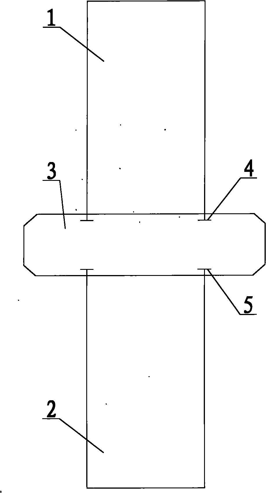
[0018] refer to figure 1 , a pipe pile structure, comprising an upper pile 1 and a lower pile 2, a support plate 3 is also provided between the upper pile 1 and the lower pile 2, and the cross-sectional areas of the upper pile 1 and the lower pile 2 are smaller than the support The cross-sectional area of ​​disk 3. The bottom of the upper pile 1 is provided with an upper connection block 4 , and the top of the lower pile 2 is provided with a lower connection block 5 , and both the upper connection block 4 and the lower connection block 5 are buried in the support plate 3 . The upper pile 1 and the lower pile 2 are rectangular parallelepiped, the four vertices at the bottom of the upper pile 1 are respectively provided with upper connecting blocks 4, and the four vertices at the top of the lower pile 2 are respectively provided with lower connecting blocks 5. The upper pile 1 is a concrete upper pile 1, the lower pile 2 is a concrete lower pile 2, the support plate 3 is a conc...

Embodiment 2

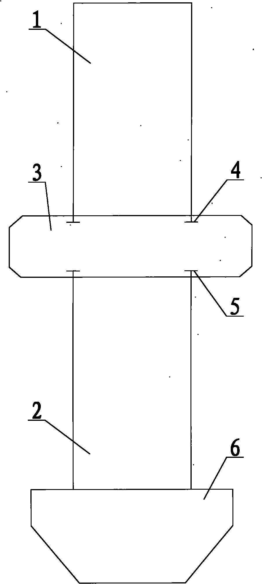
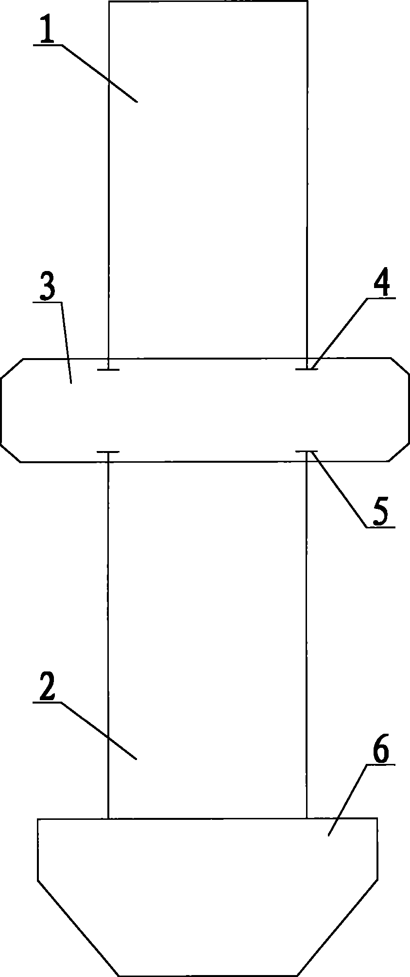
[0020] refer to figure 2 In this embodiment, on the basis of Embodiment 1, a pile head 6 is added at the bottom of the lower pile 2, and the cross-sectional area of ​​the pile head 6 is greater than that of the lower pile 2. The pile head 6 is in the shape of an inverted cone or an inverted table as a whole. The prestress of the pipe pile is further improved.


PUM


Abstract

The invention discloses a tube pile structure, which comprises an upper pile and a lower pile, wherein a supporting disc is also arranged between the upper and the lower piles, and the cross section area of both the upper and the lower piles is smaller than that of the supporting disc. The supporting disc with larger cross section area is arranged at the joint between the upper and the lower piles, so the prestress of the entire tube pile structure is stronger, and the firmness is better.

Description

【Technical field】 [0001] The invention belongs to the field of building construction, in particular to the improvement of pipe pile structures used in building construction. 【Background technique】 [0002] Compared with cast-in-situ piles, prestressed pipe piles have their own advantages: pipe piles are produced in factories, the quality is easy to control and inspect, the construction speed is fast, and the quality of piles is guaranteed compared with cast-in-situ piles (especially for soft soil foundations, immersed pipe pouring The piles are prone to broken piles due to the soil squeezing effect), the construction site has low noise, little environmental pollution, little vibration, and relatively little impact on surrounding buildings, so it is widely used in overpasses and urban viaducts. [0003] In the current construction, the pipe piles are directly welded to each other, and the force direction between the pipe pile and the soil layer is single, the prestress is poo...

Claims


Application Information

Patent Timeline
IPC IPC(8): E02D5/58E02D5/48
Inventor 姚新良
Owner 浙江大东吴集团建设有限公司
Why Eureka
Try Eureka