
Boosting clock circuit and charge pump provided with the same

A clock circuit, charge pump technology, applied in the field of charge pump, to overcome the discharge current, the effect of accumulating charge stability

Active Publication Date: 2012-08-29
SHANGHAI HUAHONG GRACE SEMICON MFG CORP
View PDF0 Cites 0 Cited by
  • Summary
  • Abstract
  • Description
  • Claims
  • Application Information

AI Technical Summary

Problems solved by technology

The resulting large discharge current will bring many bad problems, such as fast reverse (snapback) or latch-up effect
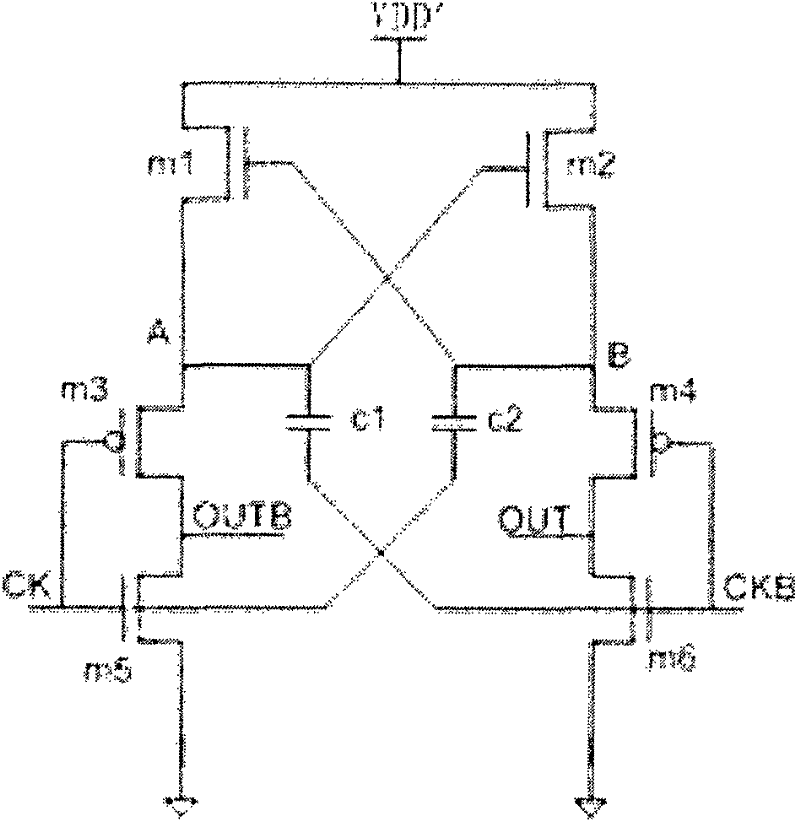
Usually, the power supply voltage VDD 1~VDDN of each single-stage boost clock circuit takes the same voltage value VDD' (such as Figure 4 Shown), sharing a voltage source, also has this problem

Method used


Image

  • Boosting clock circuit and charge pump provided with the same
  • Boosting clock circuit and charge pump provided with the same
  • Boosting clock circuit and charge pump provided with the same

Examples


Embodiment Construction

[0044] In order to make the object, technical solution and advantages of the present invention clearer, the present invention will be further described in detail below in conjunction with the accompanying drawings.

[0045] Such as figure 2 As shown, from the point of view of charging the capacitor, the capacitance of each single-stage boost clock circuit is set to C, and the charging voltage is VDD', then the charging charge of the single-stage boost clock circuit Q=C*VDD'. N stages of single-stage boosted clock circuits are connected in series; the capacitance of each stage of single-stage boosted clock circuit can be different, which are C1~CN respectively; the power supply voltage of each stage of single-stage boosted clock circuit can also be different, respectively: VDD 1~VDD N (such as image 3 shown). Then the charge Q' accumulated by the entire boost clock circuit = Q1+Q2+...+QN=C1*VDD 1+C2*VDD 2+...+CN*VDD N. To reduce the adverse effects caused by too much charg...


PUM


Abstract

The invention discloses a boosting clock circuit which comprises at least one single-stage boosting clock circuits which are cascaded and is characterized in that at least one single-stage boosting clock circuit of the boosting clock circuit is connected with a comparison and selection circuit; and the comparison and selection circuit adjusts and controls the capacitance of the single-stage boosting clock circuit connected therewith according to the supply voltage of the single-stage boosting clock circuit. A charge pump circuit comprises a charge pump and above boosting clock circuit, wherein the boosting clock circuit charges the charge pump. The boosting clock circuit and the charge pump circuit utilizes the comparison and selection circuit to adjust the charging capacitances necessaryfor all the corresponding single-stage boosting clock circuits according to the changes of the supply voltages of the single-stage boosting clock signals so as to limit the amplification factor of the boosting clock circuit and to ensure the relative stability of the total accumulated charges of the whole boosting clock circuit. The boosting clock circuit and the charge pump circuit overcome the defect that the conventional boosting clock circuit and the charge pump circuit are easy to have big discharge current.

Description

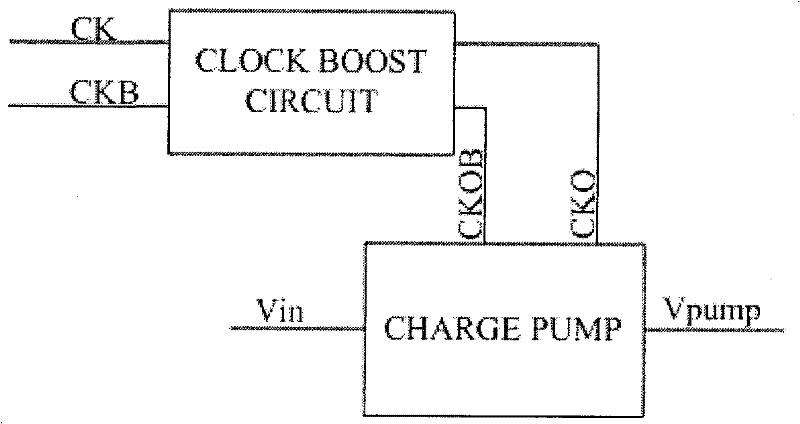
technical field [0001] The invention belongs to the technical field of charge pumps, in particular to a boost clock circuit and a charge pump with the boost clock circuit. Background technique [0002] A charge pump, also known as a switched capacitor voltage converter, is a DC-DC (DC-DC) converter that uses "flying" or "pumping" capacitors to store energy. The charge pump can make the input voltage Raised or lowered, can also be used to generate negative voltages. Traditional charge pumps control the charging and discharging of flying capacitors to multiply or reduce the input voltage by a certain factor (0.5, 2 or 3) to obtain the required output voltage. [0003] At present, commonly used charge pumps have a boost clock circuit. The input clock signal CK and the reverse clock signal CKB are boosted by the boost clock circuit and output as the clock signal CKO and the reverse clock signal CKOB; the corresponding high-low level difference VH of the clock signal CK and the...

Claims


Application Information

Patent Timeline
Patent Type & Authority Patents(China)
IPC IPC(8): H02M3/07
Inventor 杨光军
Owner SHANGHAI HUAHONG GRACE SEMICON MFG CORP
Learn More