Claw-type rotatable dynamic balance base cap clamping vice

A technology of rotational balance and dynamic balance, which is applied in the vise field, can solve problems such as difficult vise clamping smoothly, affecting clamping stability and precision, and achieves the effect of increasing practicability

Active Publication Date: 2010-07-28
洪清文
View PDF0 Cites 4 Cited by
  • Summary
  • Abstract
  • Description
  • Claims
  • Application Information

AI Technical Summary

Problems solved by technology

If this vise is applied to the workpiece 50 of clamping thin shape, it is necessary to place a support block 60 at the bottom of the workpiece 50, so that the workpiece 50 is elevated at the height near the top of the movable jaw 30 and the fixed jaw 40, and then the clamping block 301, The thin workpiece 50 is clamped by the edge of 401, but the known movable mouthpiece 30 and fixed mouthpiece 40 have a certain height H, if the clamping position is higher (the longer the force arm), the moment M generated by the reaction force N will be more Large, and there is a certain gap between the movable mouthpiece 30 and the screw rod 20, which will cause the movable mouthpiece 30 and the fixed mouthpiece 40 to rise up (tilt) in the opposite direction, affecting the stability of its clamping and the precision of post-processing. Spend
Secondly, there are all kinds of parts in the industry today, which need to be clamped by a vise to carry out processing operations. The jaws of the known vise are of a fixed shape, which cannot meet the needs of various workpiece clamping, such as thin Workpieces, round workpieces, triangular, polygonal or other irregular-shaped workpieces, and castings with rough surfaces, height gaps, workpieces with rough surfaces cut by a sawing machine, skewed workpieces, etc., are difficult to clamp smoothly with a vise

Method used


Image

  • Claw-type rotatable dynamic balance base cap clamping vice
  • Claw-type rotatable dynamic balance base cap clamping vice
  • Claw-type rotatable dynamic balance base cap clamping vice

Examples


Embodiment Construction

[0028] The features and advantages of the present invention will be described in detail below with reference to the accompanying drawings.

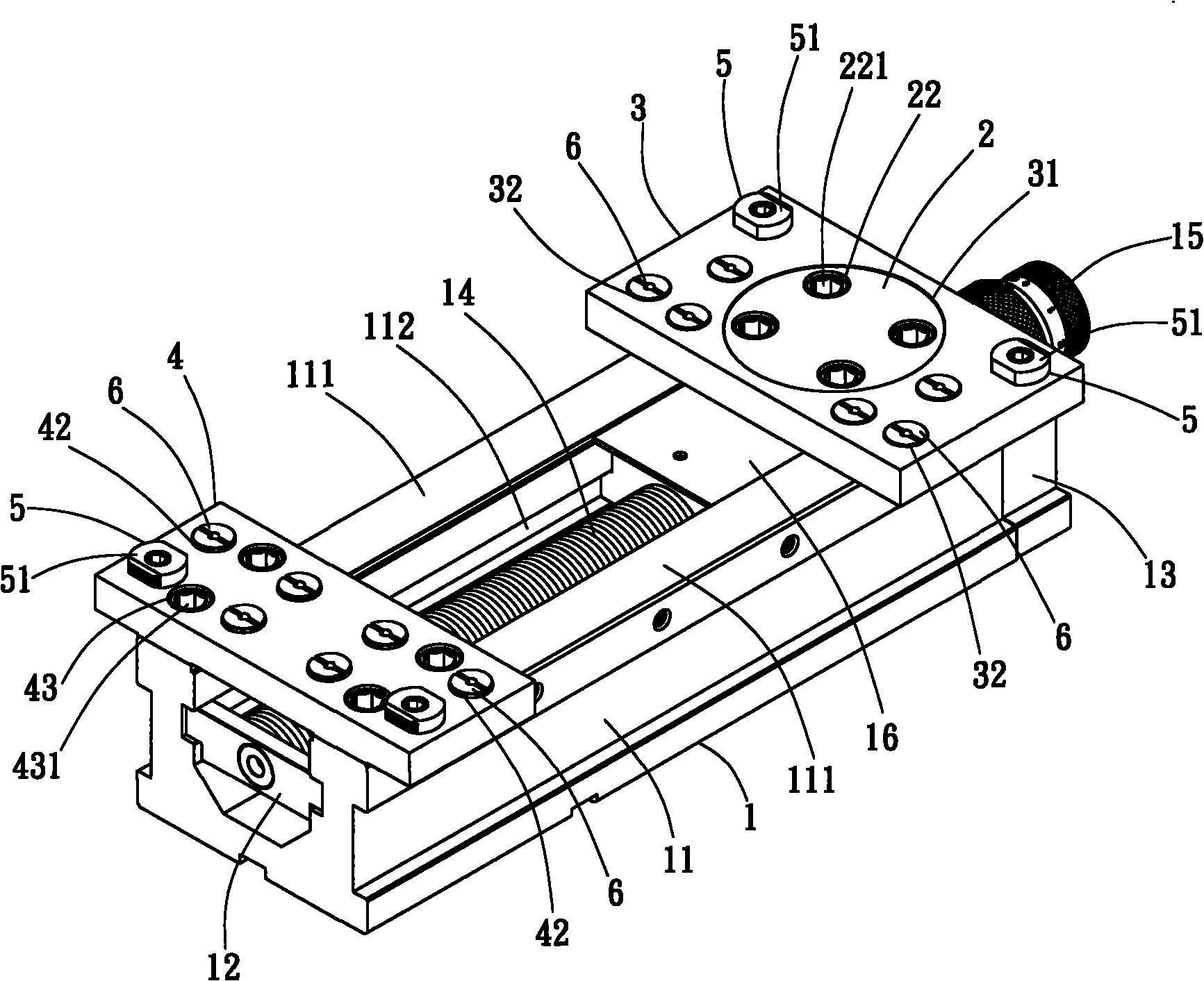
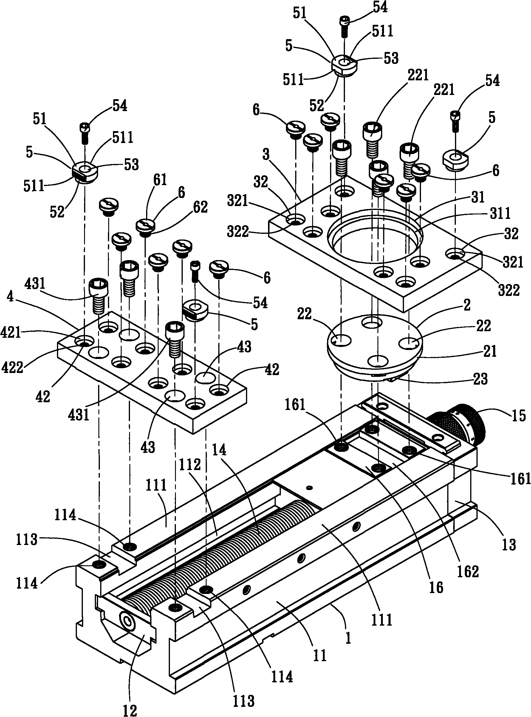
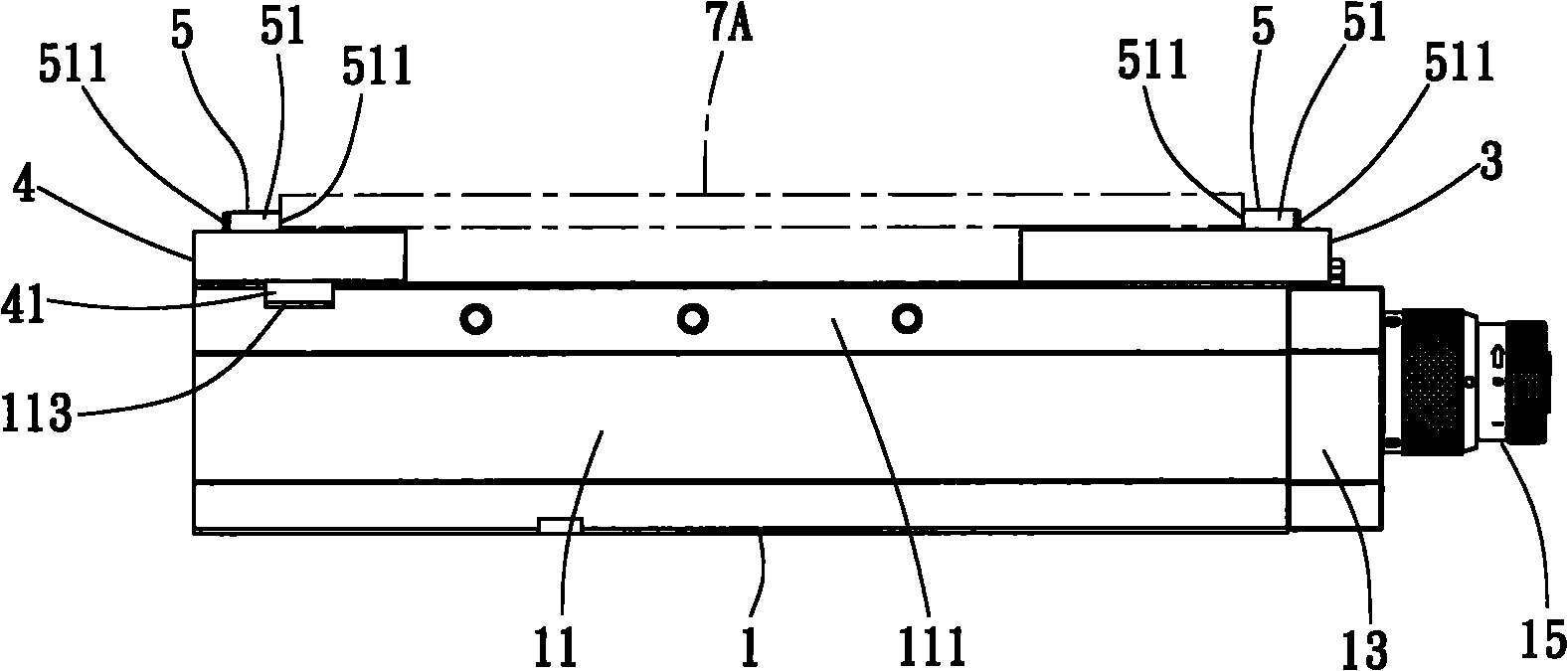
[0029] Such as figure 1 and figure 2 As shown, the claw-type rotatable rotary balance jaw clamping vise of the present invention, its preferred embodiment includes a vise body 1, a fulcrum 2, a dynamic balance jaw 3, a fixed jaw 4 and two or more clamps Claw 5 consisting of:

[0030] Vise body 1, such as figure 1 and figure 2 As shown, it includes a base 11, the base 11 is provided with two parallel slide rails 111, an accommodating chamber 112 is formed between the two slide rails 111, and a positioning groove 113 is provided at the proximal end of the slide rails 111 And one or more second fixing parts 114, the second fixing parts 114 can be screw holes. And the front end of this accommodating chamber 112 is combined with front axle seat 12, and rear end is combined with rear axle seat 13, is provided with rotatable screw rod 1...


PUM


Abstract

The invention discloses claw-type rotatable dynamic balance base cap clamping vice, comprising a vice main body, a fulcrum shaft, a dynamic balance base cap, a fixed base cap and two or more than two clamping jaws, wherein, the fulcrum shaft is fixed on a nut base at the middle of the vice main body. The dynamic balance base cap is sheathed on the fulcrum shaft, so as to lead the dynamic balance base cap to adjust the angle according to the rotation of the fulcrum shaft; the dynamic balance base cap is selected, two or more than two locating holes are arranged at the upper end of the fixed base cap and are arbitrarily combined with various clamp claws and supporting pieces, so as to form the claw-type rotatable balance base cap clamping vice; the clamping claws and the supporting pieces are utilized to clamp workpieces with rough surfaces, round and irregular shapes, so as to achieve the functions of precise and balanced clamping workpieces.

Description

technical field [0001] The invention relates to a claw-type vise clamped by a rotatable balance jaw, especially a vise with two or more jaws on a rotatable dynamic balance jaw and a fixed jaw for balanced clamping. . Background technique [0002] Known vises such as Figure 16 As shown, it is composed of vise body 10, screw rod 20, movable jaw 30, fixed jaw 40 and other components. The movable jaw 30 can move forward or backward by turning the screw 20 by the user. The clamping blocks 301 and 401 on the rear end surface of 40 clamp the workpiece 50 . If this vise is applied to the workpiece 50 of clamping thin shape, it is necessary to place a support block 60 at the bottom of the workpiece 50, so that the workpiece 50 is elevated at the height near the top of the movable jaw 30 and the fixed jaw 40, and then the clamping block 301, The thin workpiece 50 is clamped by the edge of 401, but the known movable mouthpiece 30 and fixed mouthpiece 40 have a certain height H, if t...

Claims


Application Information

Patent Timeline
IPC IPC(8): B25B1/04B25B1/24B25B1/06B25B1/10B25B1/02
Inventor 洪清文
Owner 洪清文
Why Eureka
Try Eureka