Lightweight pinch grip hanger

A technology of clothes hangers and clips, which is applied in the direction of clothes hangers, clothespins, textiles and paper making, and can solve problems such as adverse effects on operability

Inactive Publication Date: 2010-08-04
SPOTLESS PLASTICS PTY LTD
View PDF2 Cites 4 Cited by
  • Summary
  • Abstract
  • Description
  • Claims
  • Application Information

AI Technical Summary

Problems solved by technology

[0007] Ideally, however, when substantially modified hangers, such as lightweight hangers, are transported and handled by existing mech

Method used


Image

  • Lightweight pinch grip hanger
  • Lightweight pinch grip hanger
  • Lightweight pinch grip hanger

Examples


Embodiment Construction

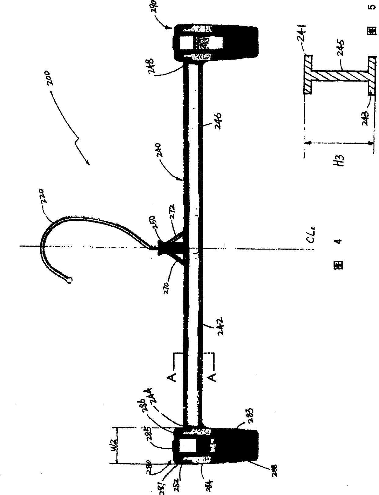
[0033] refer to figure 1 , illustrated is a pinch hanger 100 known in the prior art. The hanger has a hook part 110 and a hanger body 120 connected to the hook part 110 substantially in the middle of the body 120 . The hanger body 120 is substantially symmetrical along the centerline CL of the body, as shown.

[0034] The main body 120 has an upper portion including a centrally located protrusion 130 on which the hook member 110 is rotatably mounted. The protrusion 130 is reinforced by a pair of wings 132 and 134 on opposite sides thereof, which are integrally molded and connected to the main body 120 . Preferably, the pair of wings 132 and 134 are substantially symmetrical to each other with respect to the centerline CL of the hanger body 120 .
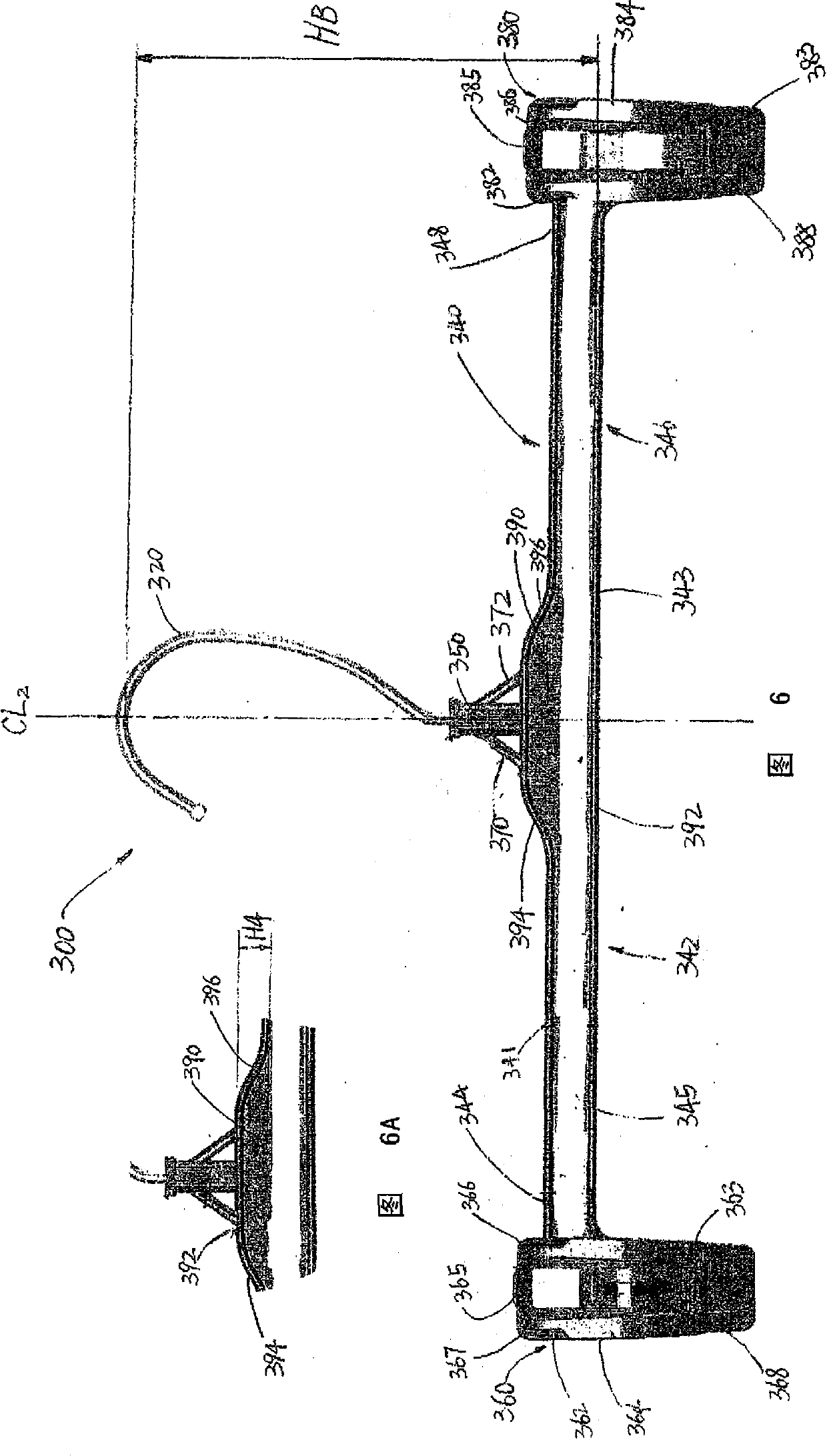
[0035]The area of ​​the hanger where the protruding portion 130 and the wings 132 and 134 are disposed and the area of ​​the hanger where the hook member 110 is connected to the main body 120 of the hanger is generally defined as ...


PUM


Abstract

In a lightweight and environmentally friendly pinch grip hanger, the height of the hanger body is reduced to have the upper ends of the jaws of the pinch grip to extend beyond the upper flange of the hanger body. This configuration reduces the weight of the hanger and saves the raw material used to mold the hanger. The hanger is environmentally friendly. The hanger further has an elevated portion formed below a lower neck region of the hanger where the hook of the hanger mounted to the hanger body. The hanger body further has a raised rib extending throughout the entire length of the hanger body.

Description

[0001] Cross References to Related Applications [0002] Pursuant to 35 U.S.C. §119(e), this application claims priority to U.S. Provisional Patent Application Serial No. 61 / 149688, filed February 3, 2009, entitled "Light Duty Pinch Clothes Hanger," for various purposes , which is incorporated herein by reference in its entirety. technical field [0003] The present invention generally relates to a molded plastic clothes hanger which is widely used for the purpose of carrying and displaying clothes. More particularly, the present invention relates to a lightweight pinch hanger with an improved hanger body and pinch clips that consumes less material and expends less energy to process the material than existing pinch hangers while improving the hanger The strength of the pinch without compromising the structural integrity and mechanical properties of the hanger. Background technique [0004] In the retail arena of selling clothes, a scheme called Clothes On Shelf (GOH) has b...

Claims


Application Information

Patent Timeline
IPC IPC(8): A47G25/48D06F55/00A47G25/28
CPCA47G25/38A47G25/485A47G25/48
Inventor S·F·古尔德森
Owner SPOTLESS PLASTICS PTY LTD
Why Eureka
Try Eureka