
Zipper slide handle, tab or pull apparatus

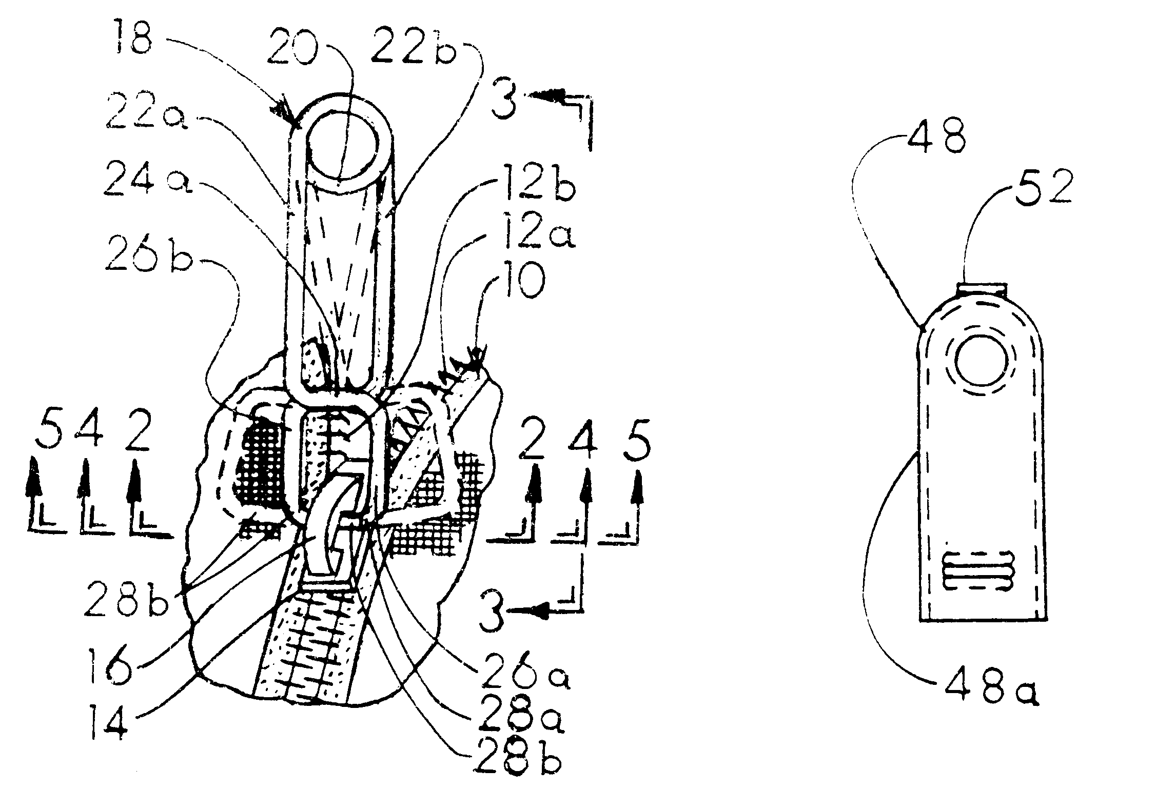
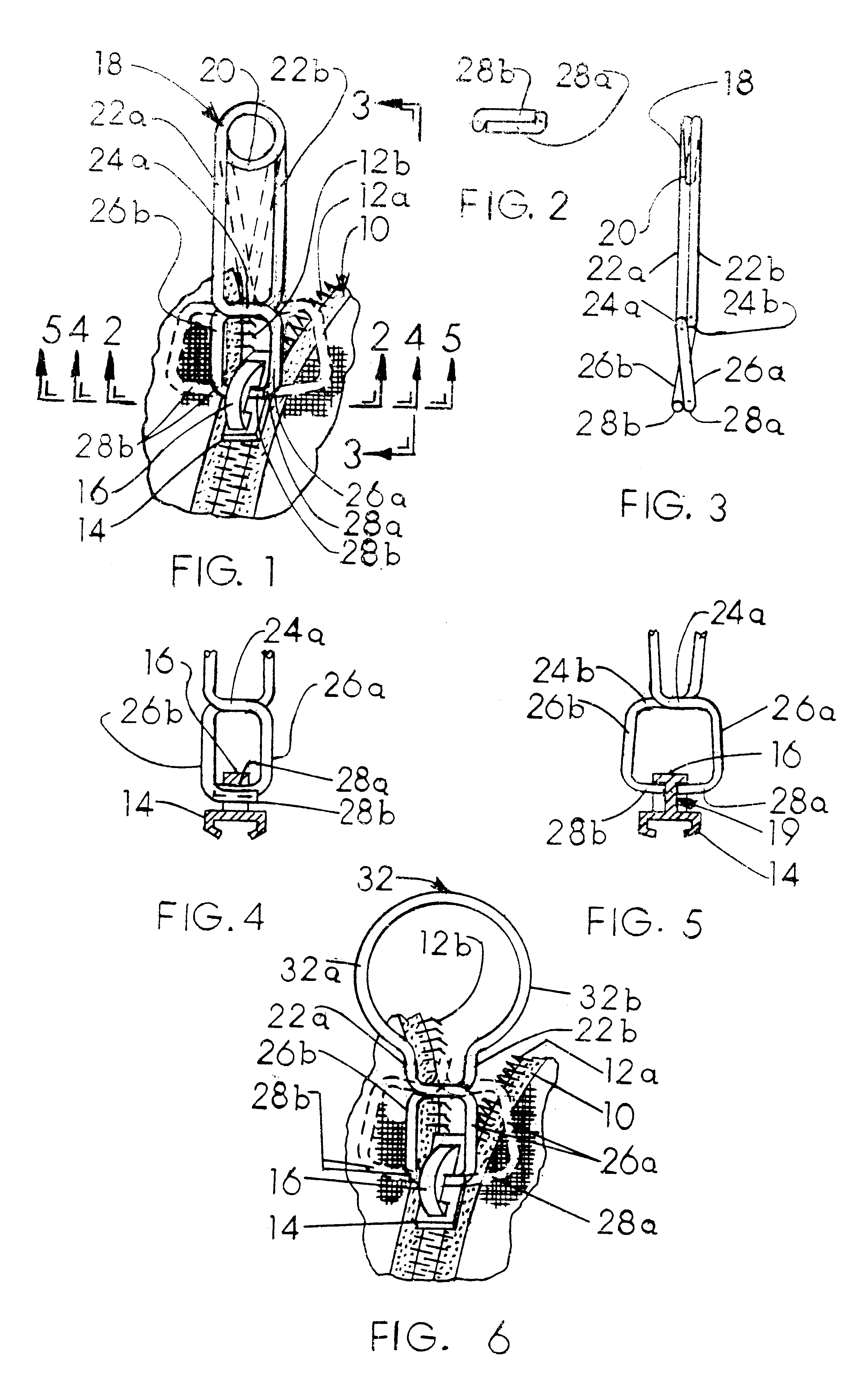
a slide handle and tab technology, applied in the field of zippers, can solve the problems of reducing the service life of the attachment area, so as to achieve the effect of convenient carrying

Inactive Publication Date: 2001-06-05
FOX WILLIAM LESTER
View PDF22 Cites 23 Cited by
  • Summary
  • Abstract
  • Description
  • Claims
  • Application Information

AI Technical Summary

Benefits of technology

to provide a cover means for the zipper handle, tab or pull which is easily secured to the handle, tab or pull and which provides additional grasping surface for the zipper user.
The present invention solves these and other similar problems in a new, novel and heretofore unobvious manner by providing an easily carried and attachable replaceable zipper slide pull to replace a lost, destroyed or damaged pull with only the human hand and fingers.

Problems solved by technology

This concentrated stress load and wear is greatly increased when the user is confronted with a temporary or repeated zipper teeth jamming problem or condition.
Eventually this excessive wear leads to the attachment area breaking down and ultimately to the loss of the pull, or to the jamming of the zipper.
Most often actual loss of the zipper pull is the usual result.
At this juncture the zipper is useless since it cannot be opened or closed.
The zipper wearer or user is left in an embarrassing predicament with an open or closed zipper in clothing or other utility item with no readily available means to extricate him or herself.
Loss of the zipper pull usually results in replacement of the complete zipper.
Even assuming reacquisition of the lost pull, there is no readily available means to reapply the broken off pull to the zipper slide tang or loop.
The wear on the pull has removed any available attachment area.
Consequently, without mechanical assistance or tools, the zipper owner is out of luck and the zipper is inoperable.

Method used


Image

  • Zipper slide handle, tab or pull apparatus
  • Zipper slide handle, tab or pull apparatus
  • Zipper slide handle, tab or pull apparatus

Examples


Embodiment Construction

Description of the Prior Zzipper Art

Conventional zippers all include at least two rows of interengagable members or teeth which must be joined together so as to cause the zipper to open and close. A slidable member or slide surrounds the rows of teeth and is normally movable back and forth along the toothed rows causing the teeth to intermesh or interengage opening and closing the zipper.

The exposed upper surface of the zipper slide is generally provided with an upstanding tang or loop which may be varied in size and shape depending upon the ultimate use to which the slide tang or loop is to be put.

In order to cause the slide to move back and forth along the rows of teeth, a handle, tab or pull (hereinafter referred to as a pull) is provided and includes an end portion which may be machine formed onto the slide. Either the tang or loop is bent around an end hole on the pull or the pull may be attached to the tang or loop in a forming operation to close the open end of the pull into ...


PUM


Abstract

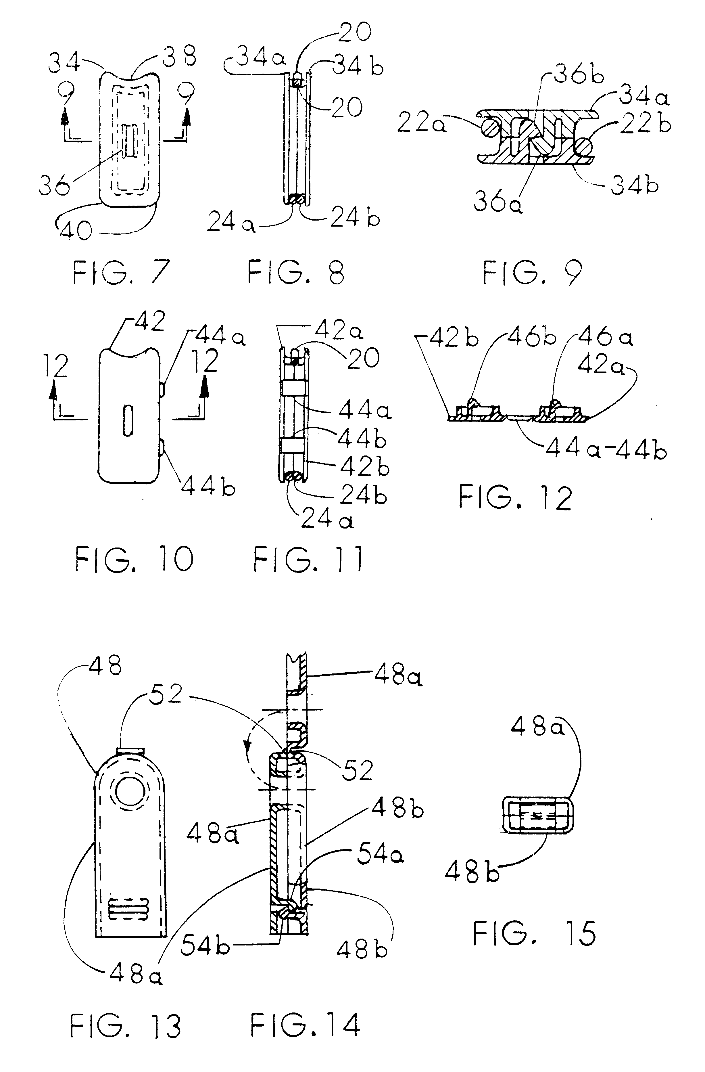
A novel handle tab or pull for a zipper which comprises a unitary wire-like resilient member having an integral spring member and including a pair of offset, spring biased gripper members which are squeezed together against the tension of the integral spring member so as to separate the gripper members so that the ends of the gripper members may then be introduced into the slide tang or loop of the zipper after which the tension of the spring biased grippers is released causing the gripper members to lock around the tang or loop of the zipper securing the novel handle, tab or pull to the zipper enabling the zipper to be operated as originally manufactured. A cover member may be employed to increase handling area of the pull. The novel zipper handle, tab or pull may be used by the zipper user to replace a lost, destroyed or damage zipper handle, tab or pull.

Description

1. Field of the InventionThe present invention relates broadly to zippers. More particularly, this invention relates to zipper handles, tabs or pulls which are attached to the movable zipper slide employed to open and close a zipper. With still more specificity, this invention relates to a new, novel and heretofore unobvious apparatus which can be installed during the zipper manufacturing phase without tools and / or subsequently be used to replace a lost, destroyed or damaged zipper handle, tab or pull.With still more specificity, this invention may include an optional cover device which can be installed over the novel handle, tab or pull for identification purposes and acts to prevent or avoid inadvertent or accidental loss of the novel handle, tab or pull from the zipper.2. Description of the Prior ArtZipper enclosure devices and apparatus are well known.Zippers are and have been utilized as closure devices with everything wearable and most things carryable. Automobile convertible ...

Claims


Application Information

Patent Timeline
Patent Type & Authority Patents(United States)
IPC IPC(8): A44B19/26A44B19/24
CPCA44B19/262Y10T24/2586
Inventor FOX, WILLIAM LESTER
Owner FOX WILLIAM LESTER
Learn More