Automated apparatus for constructing assemblies of building components

a technology for building components and automatic assembly, which is applied in the direction of programmed manipulators, other domestic objects, manufacturing tools, etc., can solve the problems of limited automatic assembly of wall panels, and achieve the effect of simplifying the build process and facilitating the automatic placement of structural members

Active Publication Date: 2013-10-31
WILLIAMS ROBOTICS
View PDF11 Cites 21 Cited by
  • Summary
  • Abstract
  • Description
  • Claims
  • Application Information

AI Technical Summary

Benefits of technology

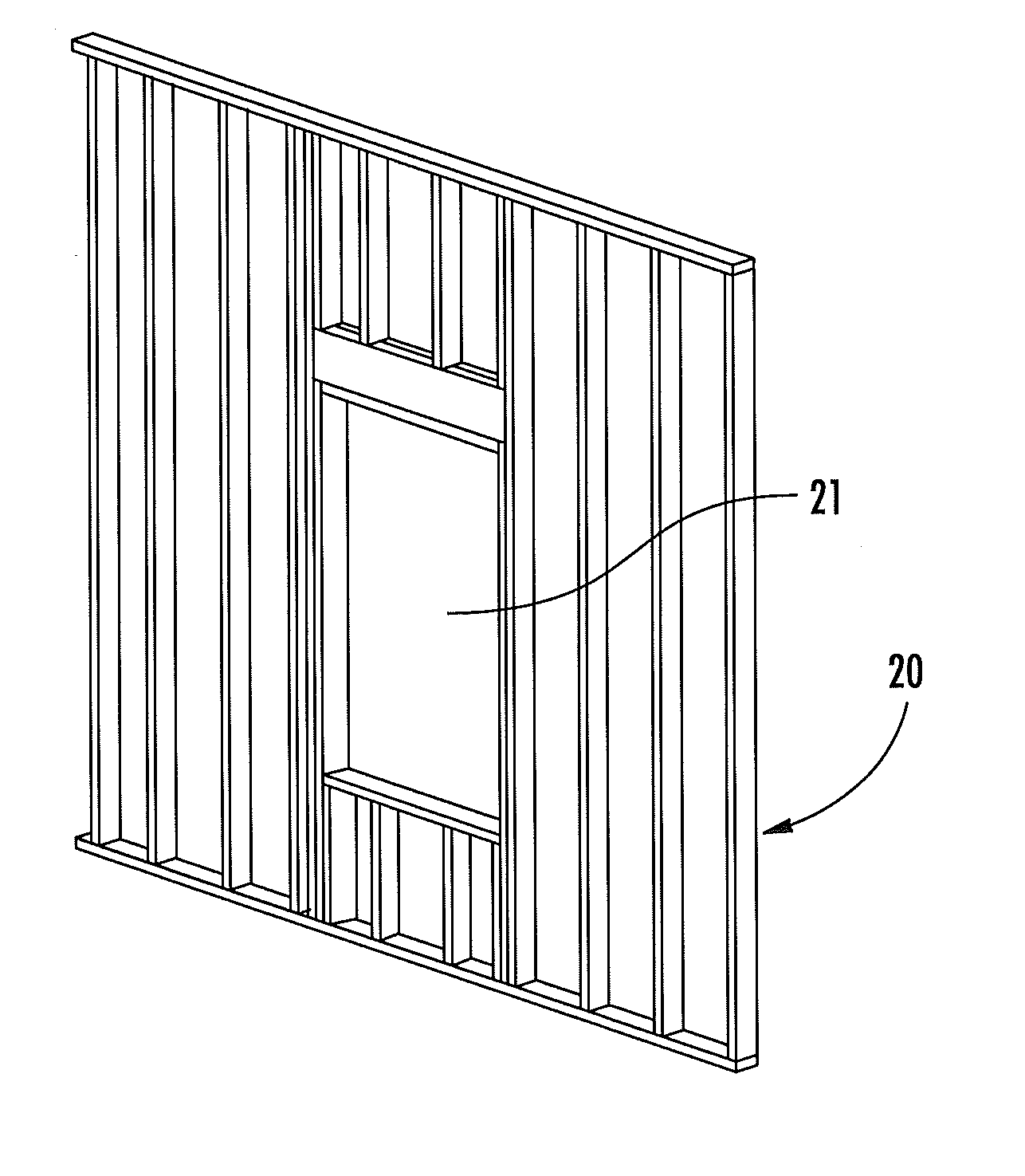
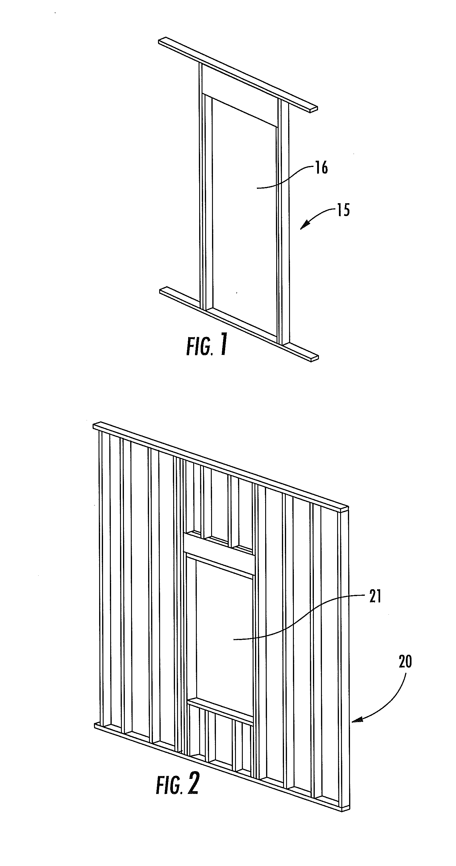
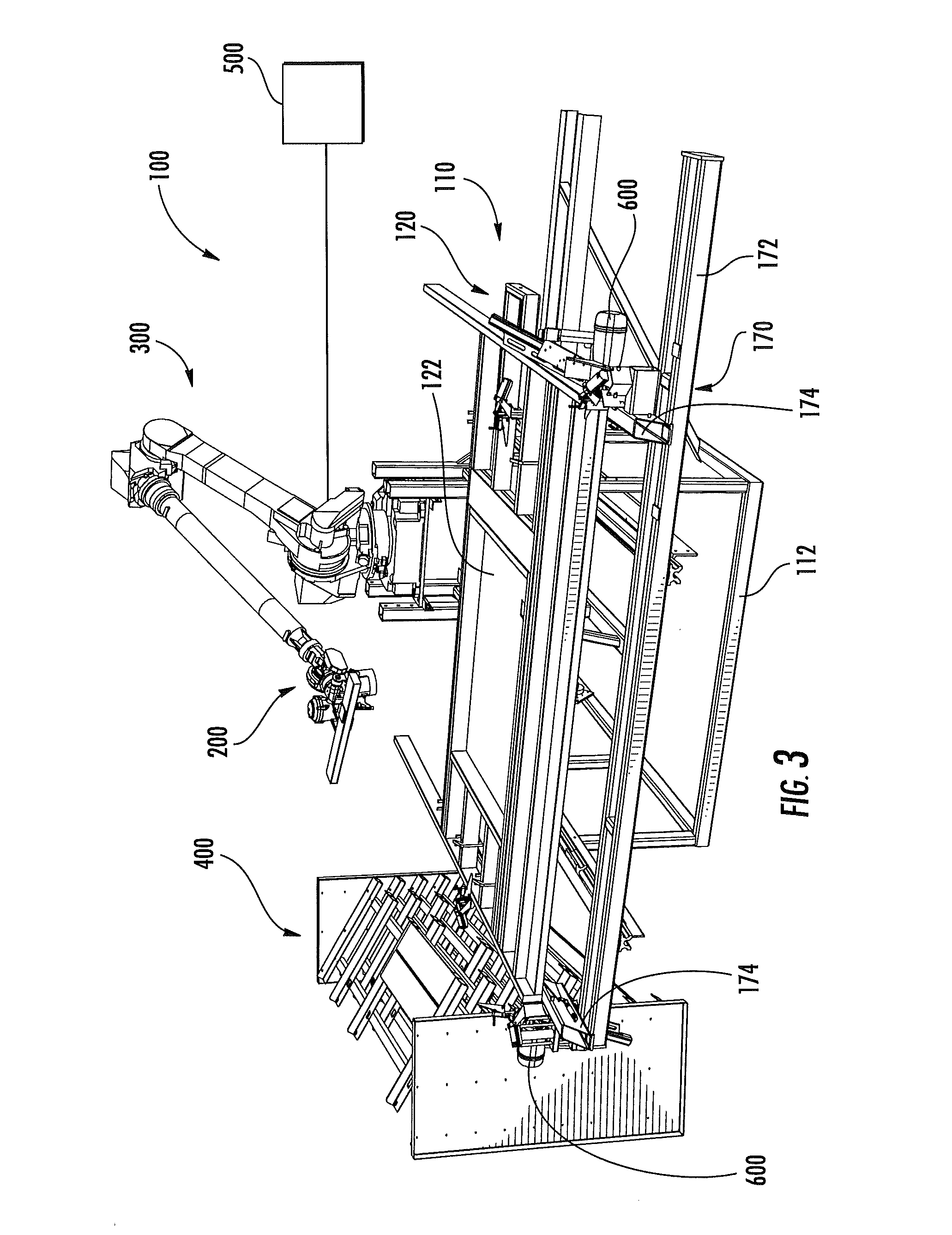
Embodiments of the present invention are directed to a system for constructing wall panels comprising a plurality of structural members. The system includes a source of structural members, a horizontal table for forming planks into wall panels, and a controller to move the table and clamp the structural members. The system can produce wall panels of almost any length by using the movable carriage. A method of constructing a wall panel includes clamping structural members with the first and second clamping units, forming a subassembly of structural members, clamping the subassembly with the second clamping unit, releasing the first clamping units, and moving the subassembly relative to the stationary table section. The method can automate the placement of structural members in tight places and simplify the build process. A method of placing a structural member includes positioning a first structural member on a build surface, positioning a second structural member on the build surface, and positioning a third structural member on the build surface, using the second structural member as a positioning fixture. This technique allows some structural members to self-fixture for other structural members.

Problems solved by technology

As a result, automation of the wall panel fabrication process has been limited.

Method used


Image

  • Automated apparatus for constructing assemblies of building components
  • Automated apparatus for constructing assemblies of building components
  • Automated apparatus for constructing assemblies of building components

Examples


Embodiment Construction

[0042]The present invention will be described more particularly hereinafter with reference to the accompanying drawings. The invention is not intended to be limited to the illustrated embodiments; rather, these embodiments are intended to fully and completely disclose the invention to those skilled in this art. In the drawings, like numbers refer to like elements throughout. Thicknesses and dimensions of some components may be exaggerated for clarity.

[0043]Unless otherwise defined, all terms (including technical and scientific terms) used herein have the same meaning as commonly understood by one of ordinary skill in the art to which this invention belongs. It will be further understood that terms, such as those defined in commonly used dictionaries, should be interpreted as having a meaning that is consistent with their meaning in the context of the relevant art and will not be interpreted in an idealized or overly formal sense unless expressly so defined herein.

[0044]In addition, ...


PUM

PropertyMeasurementUnit
Timeaaaaaaaaaa
Lengthaaaaaaaaaa
Sizeaaaaaaaaaa

Abstract

A system for constructing wall panels comprising a plurality of structural members includes: a source of structural members of predetermined size; a horizontal table configured to support planks as they are being formed into a wall panel, the table including a stationary section and a movable carriage that is configured to move in a longitudinal direction toward and away from the stationary section; an articulated arm unit having a gripper, the articulating arm unit positioned to retrieve boards from the source with the gripper and place them on the table; at least one first clamping unit mounted to the stationary section for clamping structural members thereto; at least one second clamping unit mounted to the movable carriage for clamping structural members thereto; and a controller that controls the movement of the articulating arm unit and the movable carriage.

Description

RELATED APPLICATIONS[0001]This application claims the benefit of and priority from U.S. Provisional Patent Application No. 61 / 387,192, filed Sep. 28, 2010, the disclosure of which is hereby incorporated herein in its entirety.FIELD OF THE INVENTION[0002]This invention relates generally to construction of buildings, and more particularly relates to devices for the construction of wall panels and subassemblies thereof.BACKGROUND OF THE INVENTION[0003]Wall panels for the wall of a dwelling typically comprise a series of lumber boards arranged in a predetermined pattern and nailed together. Wall panel design varies from house to house because of consumer demand for individualized home design, although in some instances multiple wall panels for the same house will have the same arrangement. Most wall panels will include top and bottom horizontal boards and a number (often determined by a building code) of vertical boards to provide support. Often two or more vertical boards will be arran...

Claims


Application Information

Patent Timeline
IPC IPC(8): E04B2/00
CPCE04B2/00B27F7/003B25J9/1687B27F7/006E04B2/70Y10T29/49629Y10T29/53
Inventor WILIAMS, JEFFREY P.
Owner WILLIAMS ROBOTICS
Why Eureka
Try Eureka