
Device and method for tensioning an elongate member

a technology of flexible elongate member and elongate member, which is applied in the field of elongate member tensioning, can solve the problems of surgical elongate member shifting from the injured area, inability to maintain tension level, and inability to provide stability and support. , to achieve the effect of simplifying the installation process, improving the control of tension, and enhancing safety

Inactive Publication Date: 2012-09-13
SONOMA ORTHOPEDIC PROD INC
View PDF0 Cites 24 Cited by
  • Summary
  • Abstract
  • Description
  • Claims
  • Application Information

AI Technical Summary

Benefits of technology

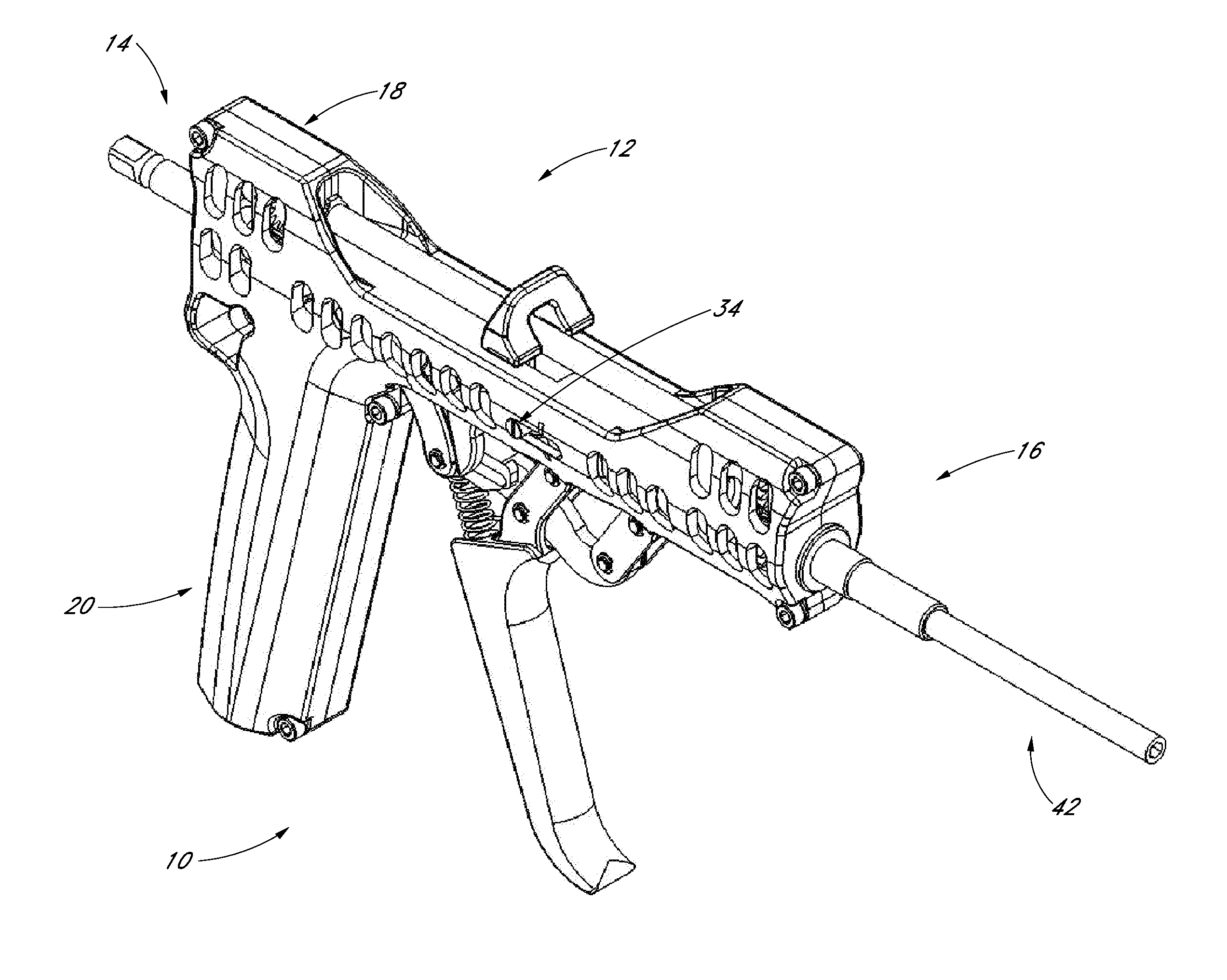
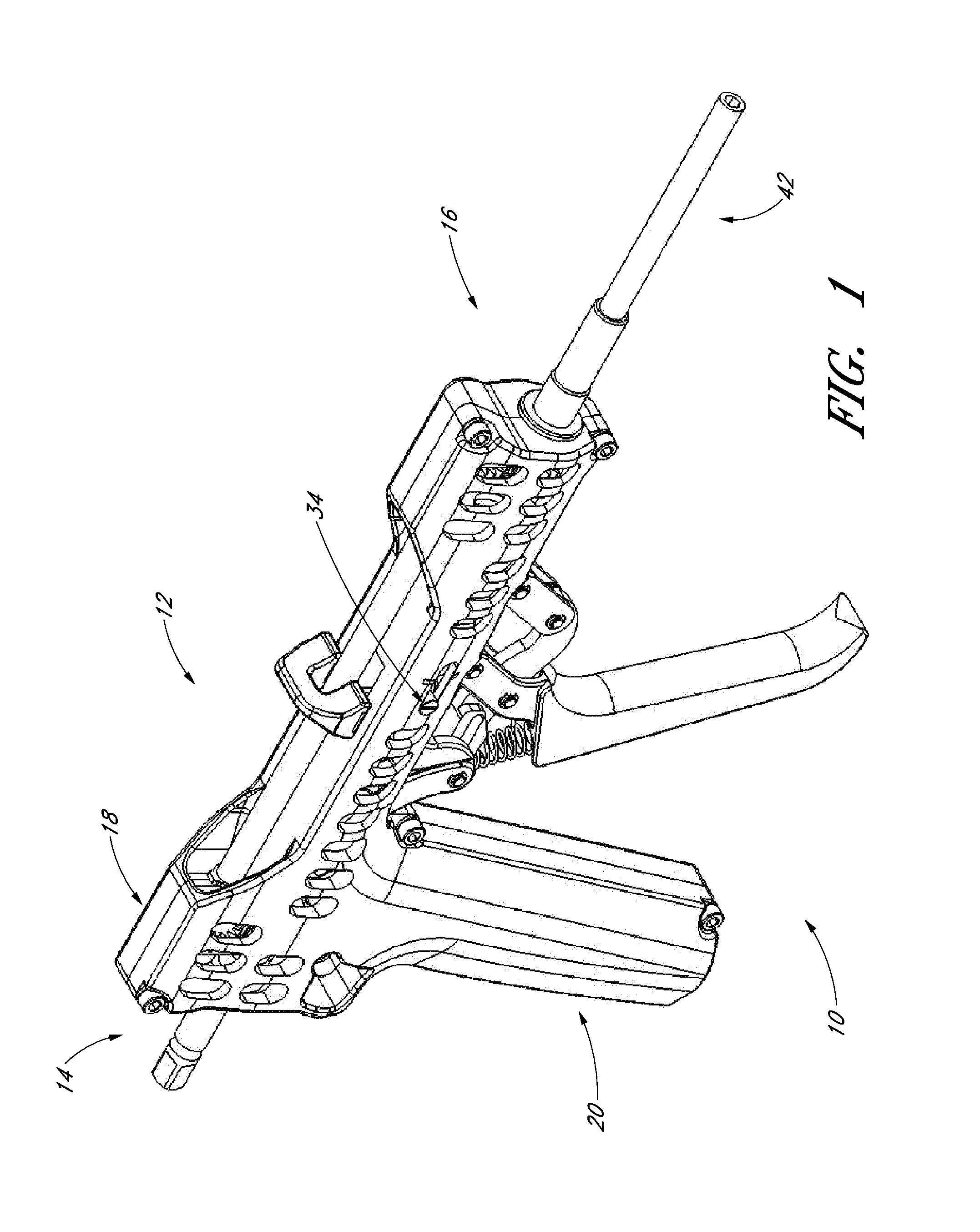
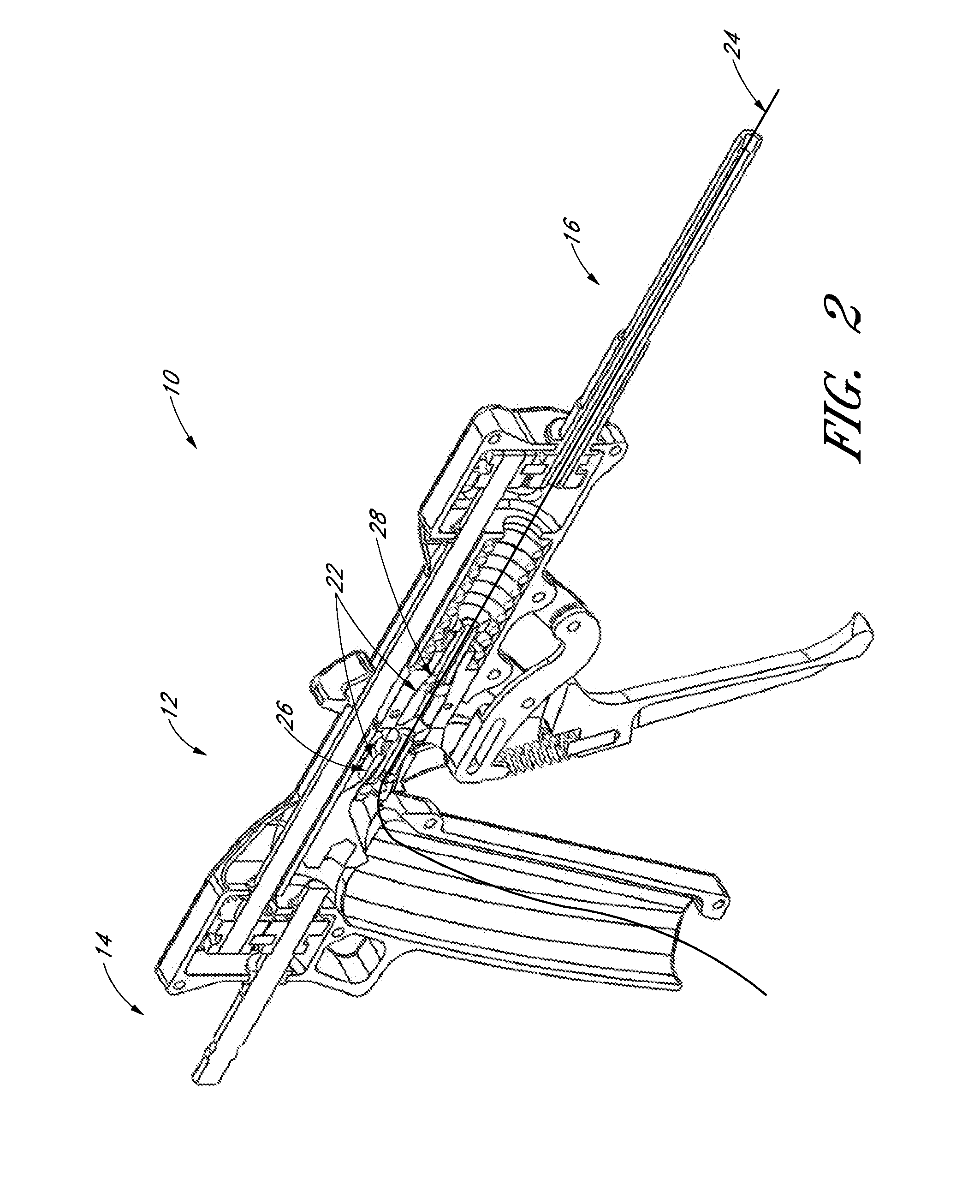
[0009]A tensioning device that provides continuous and uninterrupted adjustment could provide improved control of tension imparted to an elongate member. Additionally, a tensioning device with the ability to secure an elongate member would remove the need for separate tools, enhance safety, and simplify the installation process. To those ends, the disclosed inventions generally seek to provide full tension control of an elongate member and the independent ability to secure an elongate member under tension.
[0011]Some embodiments comprise a plurality of grippers. In one embodiment, the grippers are aligned to permit an elongate member with proximate and distal ends to pass unimpeded in one direction. In other embodiments, the grippers are not aligned. In one embodiment, the grippers permit the elongate member to freely move in the proximate direction, but prevent the elongate member from moving in the distal direction. Thus, when the distal end of the elongate member is fixed, the grippers can impart tension to the elongate member and prevent such tension from being released.

Problems solved by technology

However, by the nature of the ratchet, such tensioners have adjustment that is limited to the spacing of the ratchet teeth.
Thus, such tensioners generally cannot maintain levels of tension that do not correspond with the location of the ratchet teeth.
If the tension in the surgical elongate member is too slight, the surgical elongate member can shift from the injured area and fail to provide the stability and support desired.
On the other hand, if the surgical elongate member is too highly tensioned, it can cause injury to the patient's body or other implanted devices.
As stated, such mechanisms have adjustment limited to the ratchet tooth spacing.

Method used


Image

  • Device and method for tensioning an elongate member
  • Device and method for tensioning an elongate member
  • Device and method for tensioning an elongate member

Examples


Embodiment Construction

[0024]In accordance with the present disclosure, various embodiments of a device and method for tensioning an elongate member are provided. An elongate member can be any flexible elongated member capable of maintaining tension up to its yield strength, such as but is not limited to, wire, cable, tether, rod, threaded rod, rope, line, chain, twine, yarn, and string. An elongate member can be a variety of materials, such as but not limited to, copper, steel, iron, tin, silver, gold, cotton, hemp, sisal, nylon, aramids, polyester, and polypropylene. Depending on the application, an elongate member can be monofilament or multifilament, stranded or unstranded, coated or uncoated, sheathed or unsheathed. Use of terms related to embodiments of elongate members can be used interchangeably and should be understood to refer to the various types of embodiments of the elongate member being used. For example, cable can be used to describe any number of types of elongate members, but should not b...


PUM


Abstract

An elongate member having a fixed end is passed through a plurality of grippers that impart tension in the elongate member and prevent the tension from being released. At least one gripper is movable while at least one other can be fixed. The movable gripper travels along the elongate member toward the fixed end then reverses direction, grips the elongate member, and carries the elongate member away from the fixed end, thereby creating tension in the elongate member. At least one gripper prevents the tension from being released. In some embodiments, the elongate member passes through a rotatable shaft with a lumen. The shaft can be in communication with a crank, whereby operation of the crank rotates the shaft.

Description

BACKGROUND[0001]1. Field of the Invention[0002]Embodiments of the present invention relate to tensioning a flexible elongate member, such as a wire, cable, or tether. Some embodiments relate to the use of an elongate member in surgical applications, such as use in a segmented intramedullary or IM nail, which is used in the treatment of long bone fractures.[0003]2. Description of the Related Art[0004]The use of elongate members is well known in the art. Elongate members are used to conduct electrical current, support bridges and buildings, and carry data worldwide virtually instantaneously. An elongate member can be any flexible elongated member capable of maintaining tension up to its yield strength, such as but not limited to, wire, cable, tether, rod, threaded rod, rope, line, chain, twine, yarn, and string. An elongate member can be a variety of materials, such as but not limited to, copper, steel, iron, tin, silver, gold, cotton, hemp, sisal, nylon, aramids, polyester, and polyp...

Claims


Application Information

Patent Timeline
IPC IPC(8): A61B17/00
CPCA61B17/8869
Inventor VELDMAN, MICHAEL SCOTTBEALE, JEFFREY WARRENHUMPHRIES, JR., ROBERT H.BAYER, HANSPETER ROBERT
Owner SONOMA ORTHOPEDIC PROD INC
Learn More