Weft gripping mechanism for shuttleles weaving machines

A technology of weft yarn and loom is applied in the field of weft yarn clamping mechanism and weft yarn tensioning device, which can solve the problems of no similar existing technology, and achieve the effects of improving clamping force, eliminating friction action and good tension control.

Active Publication Date: 2019-06-04
桑贾伊库尔库特
View PDF6 Cites 0 Cited by
  • Summary
  • Abstract
  • Description
  • Claims
  • Application Information

AI Technical Summary

Problems solved by technology

[0003] 1. Indian patent - no similar prior art in textile and loom field
[0004] 2. US patent - no similar prior art in textile and loom field
[0005] 3. European patent - no similar prior art in the field of textile and weaving machines
This operation is performed just like a normal thread shedding, but the only changes that exist are in the timing

Method used


Image

  • Weft gripping mechanism for shuttleles weaving machines
  • Weft gripping mechanism for shuttleles weaving machines
  • Weft gripping mechanism for shuttleles weaving machines

Examples


Embodiment Construction

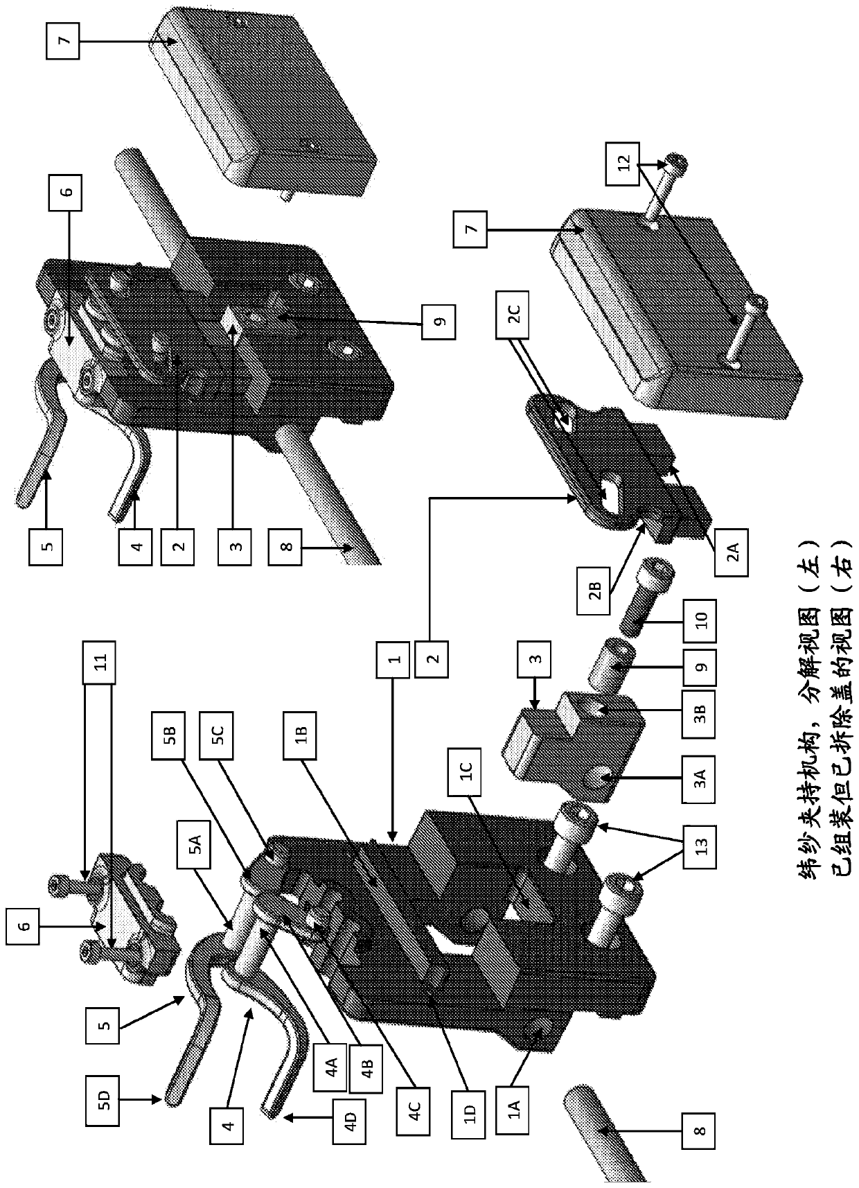
[0020] Patent description figure 1 : Weft clamping mechanism, exploded view (left), assembled but cover removed view (right).

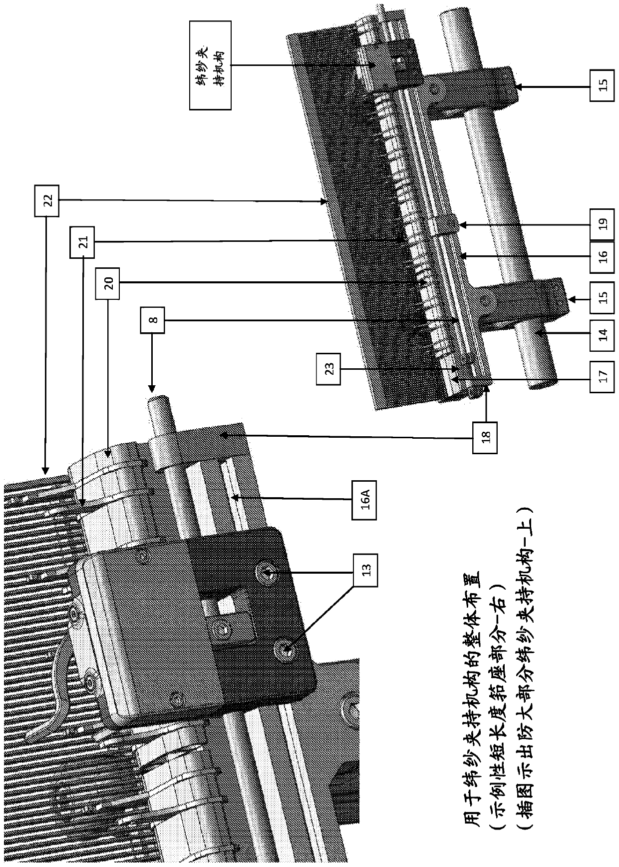
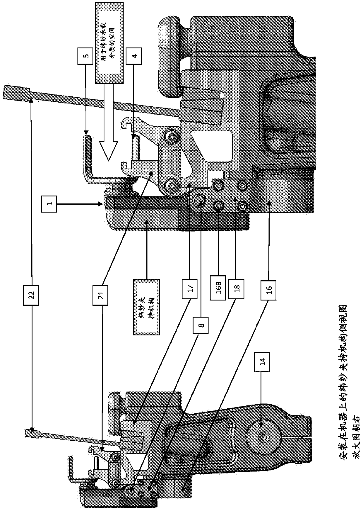
[0021] The main body (1) of the weft clamping mechanism is firmly mounted on a part (numbered 16 and further explained), which is directly mounted on the sley support of the loom so that it can be woven relative to the fabric being woven. The side moves sideways in the desired position and can be locked in place for operation. This is better explained in the description of Patent Note 2 below. The main body (1) has the following details built-in, the hole (1A) for the shaft (8) is provided in the main body (1) of the weft clamping mechanism, and the protrusion (1B) is provided on the main body (1) for braking The plate cam (2) is allowed to move sideways to the plate cam (2), and a small space (1C) for the slider part (3) is provided on the main body (1). A suitable number of holes (1D) are provided in the main body in order to install the fasteners (1...


PUM


Abstract

The invention refers to a path breaking and pioneering effort to art a Weft Gripping mechanism for use on shuttle-less weaving machines. There is no such or similar device in existence today and the need for such a mechanism arises from the key points of disadvantages of the existing systems. With the advent of the Weft Gripping mechanism, the rubbing action between the weft insertion media and boundary selvedge threads is totally eliminated and so will be the breakages arising due to the rubbing. It not only facilitates precision timing of positive grip but also improves the gripping force exerted on the weft yarn and brings about a better tension control of the weft thread, which is known to be the key element for a better fabric appearance. The novel weft grip mechanism allows a more precision timing setting of weft grip, which in turn means exact or optimum weft protruding length, which obviously means lesser wastage of precious weft yarns.

Description

Technical field [0001] The invention relates to the field of textile engineering, and more particularly to a device for tensioning weft yarns on a shuttleless loom. For decades, on shuttleless looms, selvedge selvedge or false selvedge is the only method that can be used for this purpose. [0002] The invention relates to a weft clamping mechanism used on a rapier-type shuttleless loom. There is no such or similar device, and the need for such a mechanism stems from the key shortcomings of the existing system explained further below. Background technique [0003] 1. Indian patent-there is no similar prior art in the field of textiles and weaving machines. [0004] 2. US Patent-There is no similar prior art in the field of textiles and weaving machines. [0005] 3. European patent-there is no similar prior art in the field of textiles and weaving machines. [0006] A conventional catch or false edge former is a set of selvedge threads used to hold the weft yarn. This operation is per...

Claims


Application Information

Patent Timeline
Patent Type & Authority Applications(China)
IPC IPC(8): D03D47/23
CPCD03D47/125
Inventor 桑贾伊·库尔库特
Owner 桑贾伊库尔库特
Why Eureka
Try Eureka