
Hot-fillable blow molded container with pinch-grip vacuum panels

a vacuum panel and hot-filling technology, which is applied in the direction of container preventing decay, sealing, transportation and packaging, etc., can solve the problems of product damage, less pleasing appearance of the container, and the arcuate surface between the grip- or pinch-grip-vacuum panel is unavailable to receive other generally recessed vacuum panels in addition to those used for the grip

Active Publication Date: 2007-11-20
AMCOR RIGID PLASICS USA LLC
View PDF33 Cites 24 Cited by
  • Summary
  • Abstract
  • Description
  • Claims
  • Application Information

AI Technical Summary

Problems solved by technology

If the container should collapse in an un-uniform manner, the container appearance becomes less pleasing and the customer becomes reluctant to purchase, believing the product damaged.
Packagers often place one or more spot labels on arcuate container surfaces between the grip-vacuum panels that often have a plurality of relatively shallow recessed ribs to increase rigidity, thus rendering these arcuate surfaces between the grip- or pinch-grip-vacuum panels unavailable to receive other generally recessed vacuum panels in addition to those used for the grip.
Containers having only two large diametrically apposed vacuum panels and the generally circular cross-sectional configuration are particularly vulnerable to unwanted changes-in-shape if the panels do not properly accommodate the vacuum related forces often causing the container to twist and assume a more oval cross-sectional or skewed oval cross-sectional configuration generally unpleasing to the consumer or customer.
Accordingly, containers lighter in weight are particularly vulnerable to unwanted changes-in-shape, a particular problem for containers having the pinch-grip and otherwise a generally circular cross-sectional configuration featuring only two diametrically apposed vacuum panels with spot-labeling surfaces between.

Method used


Image

  • Hot-fillable blow molded container with pinch-grip vacuum panels
  • Hot-fillable blow molded container with pinch-grip vacuum panels
  • Hot-fillable blow molded container with pinch-grip vacuum panels

Examples


Embodiment Construction

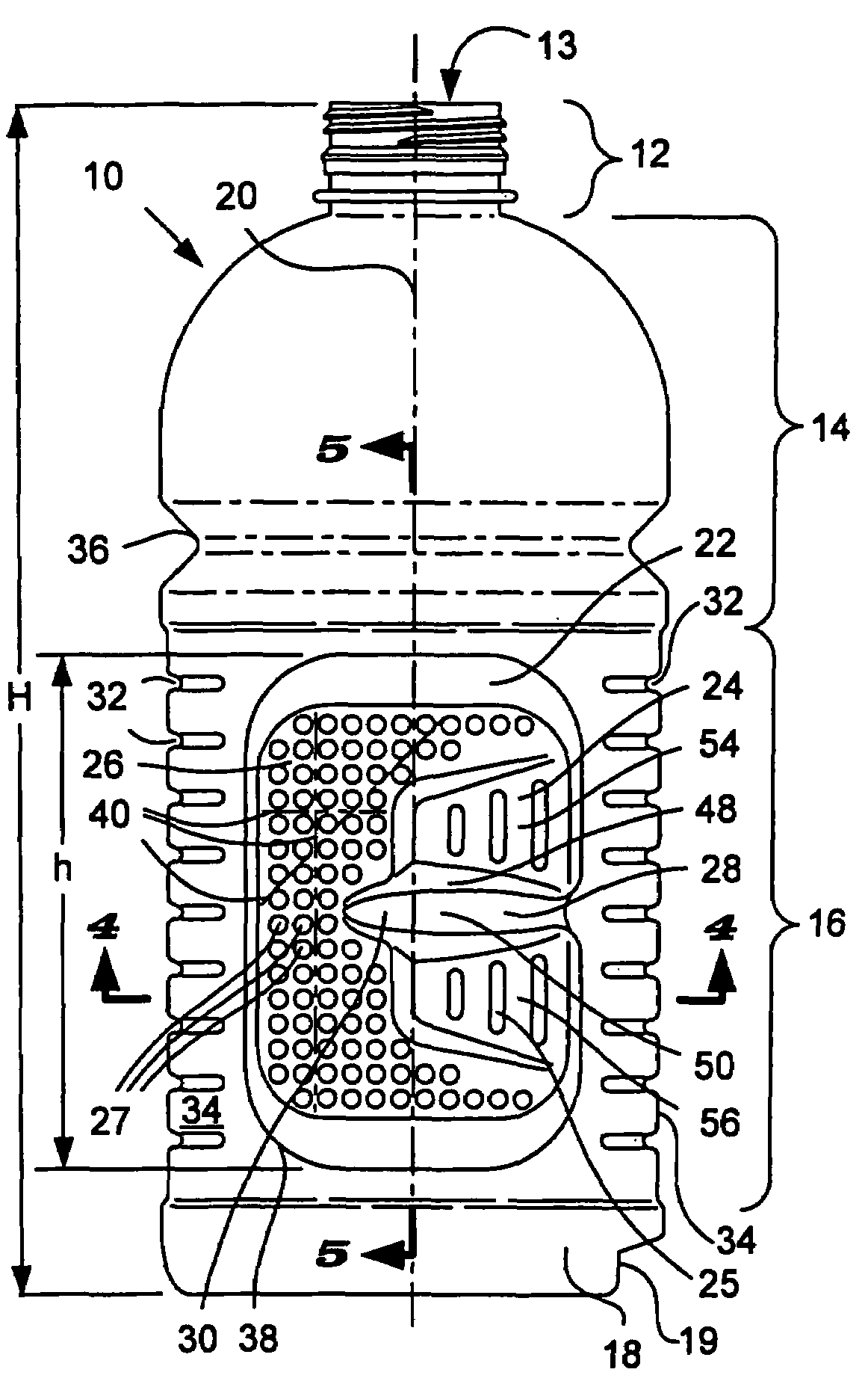
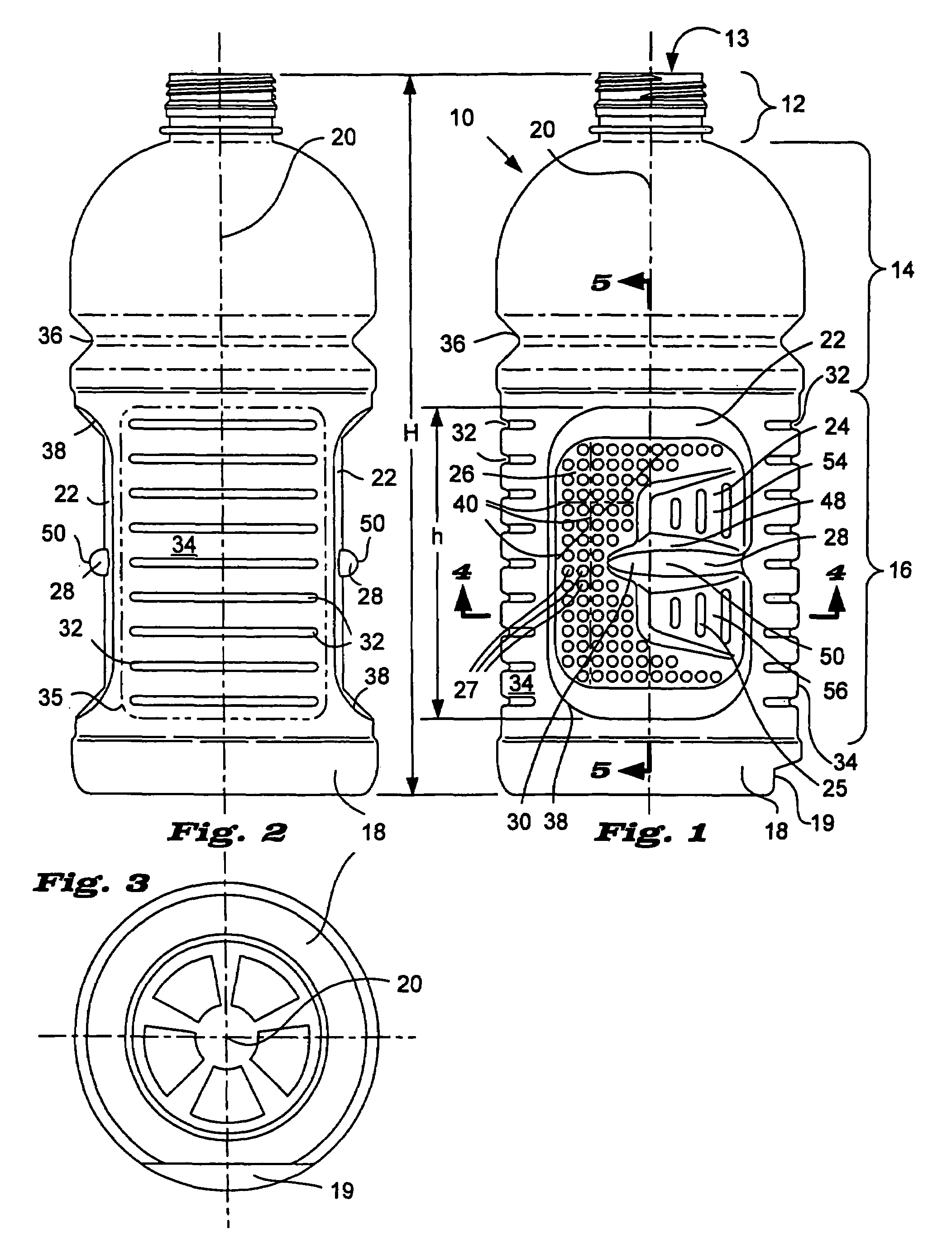
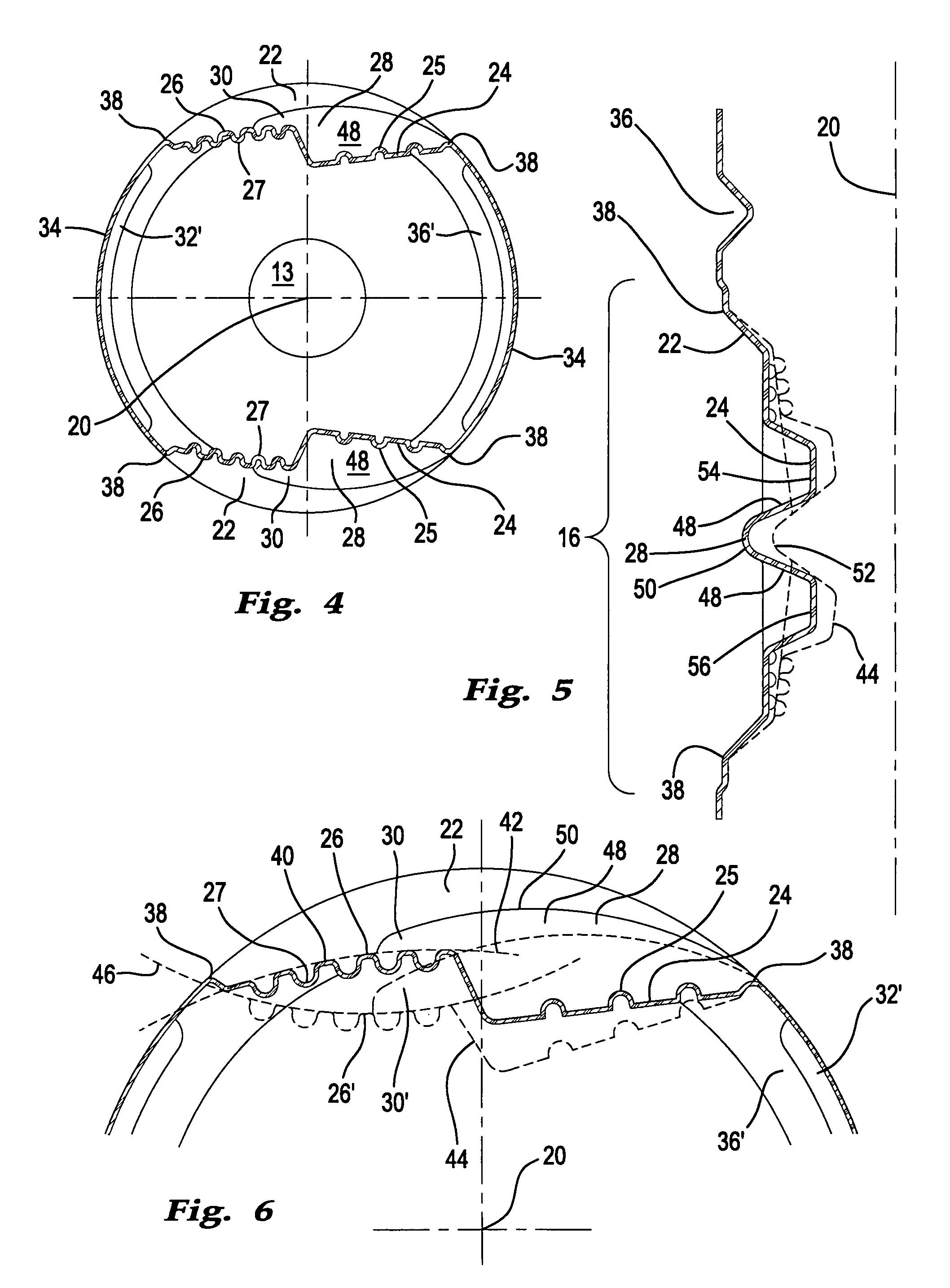
[0021]FIG. 1 illustrates a hot-fillable container 10 made of a polymer material, such as polypropylene, polyethylene terephthalate (PET), or other polymer materials. Container 10 has a neck finish portion 12 with an opening 13 suitable to receive a closure (not shown), a shoulder portion 14, a body portion 16, and a bottom portion 18 all having a centerline 20.

[0022]Body portion 16 features an indented vacuum panel 22 having a pinch-grip 24 with grip ridges 25, a flexible-field 26, and a bridge 28 with a tongue 30 extending across pinch-grip 24 and into flexible-field 26. Container 10 has an overall height H. To be most effective, vacuum panel 22 has a height h approximating that of body portion 16 that in turn is approximately 50 to 75 percent of the container 10 height H. Those skilled in the art realize grip ridges 25 create indentations that allow fingers and thumb of an average hand to effectively secure a hold to the container 10 while handling and can be any convenient config...


PUM


Abstract

A polymer container suitable for hot-filling featuring a pinch-grip vacuum panel combination having a flexible-field and a generally ridged pinch-grip that accommodates vacuum related forces.

Description

TECHNICAL FIELD OF INVENTION[0001]This invention generally relates to a hot-fillable, blow molded container made of polymer materials, such as polyethylene terephthalate (PET) or other similar polyester materials, having at least one pair of panel sections capable of resisting undesirable deformation that accommodates reductions in product volume during cooling of a hot-filled product. The container has a pinch-grip within each of the at least one pair of panel sections facilitating container handling by a consumer.BACKGROUND[0002]Packagers, to ensure adequate sterilization, often fill bottles and containers with liquids or products at an elevated temperature of approximately 180° F. to 205° F. (82° C. to 96° C.) and seal with a closure before cooling. Manufacturers generally refer to this as a “hot-fill” container or as a “hot-filling” process. As the sealed container cools, a slight vacuum, or negative pressure, forms inside causing the container to slightly change shape, particul...

Claims


Application Information

Patent Timeline
Patent Type & Authority Patents(United States)
IPC IPC(8): B65D1/02B65D23/10
CPCB65D79/02B65D1/0223
Inventor LANE, MICHAEL T
Owner AMCOR RIGID PLASICS USA LLC
Learn More