Waste gas central treating system

A centralized treatment and exhaust gas technology, applied in the direction of cells, electrolytic processes, electrolytic components, etc., can solve problems such as difficult to adjust air volume, unfavorable energy saving, over-design, etc.

Inactive Publication Date: 2012-01-11
惠州益伸电子有限公司
View PDF0 Cites 0 Cited by
  • Summary
  • Abstract
  • Description
  • Claims
  • Application Information

AI Technical Summary

Problems solved by technology

However, there are still the following shortcomings to be solved with the traditional extraction and scrubber tower to treat exhaust gas: 1) The traditional extraction and scrubber is only equipped with a single suction fan, which is difficult to adjust the air volume, so when using this The suction fan is basically fully open or fully closed, which is not conducive to energy saving; 2) Due to the characteristics of the suction fan: the ability to push the wind (wind pressure 20-50mm water column pressure difference) is far greater than the suction ability ( Wind pressure 2-10mm water column pressure difference), in order to meet the effect of the air volume, it is usually necessary to increase the diameter of the induced air pipe, that is, the horsepower of the induced draft fan to avoid too much pressure loss, which not only increases the cost of installation, but also increases the daily operation. 3) Using one scrubber to treat waste gas from different sources and properties at the same time puts pressure on the design of the scrubber, because the design must meet the maximum processing capacity, and after the completion of the production, Impossible to increase throughput requirements (augmented hood), which often results in overdesign

Method used


Image

  • Waste gas central treating system
  • Waste gas central treating system
  • Waste gas central treating system

Examples


Embodiment Construction

[0013] The present invention will be further described in detail below in conjunction with the accompanying drawings and embodiments.

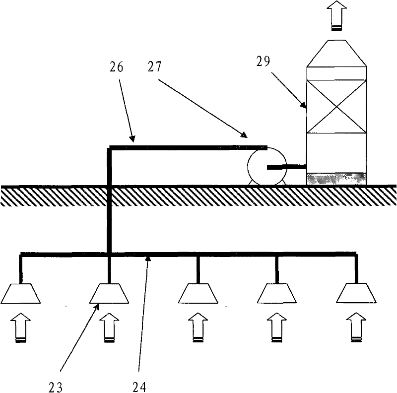
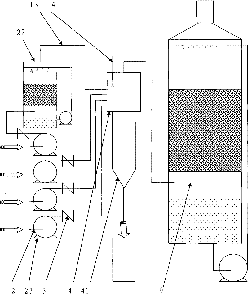
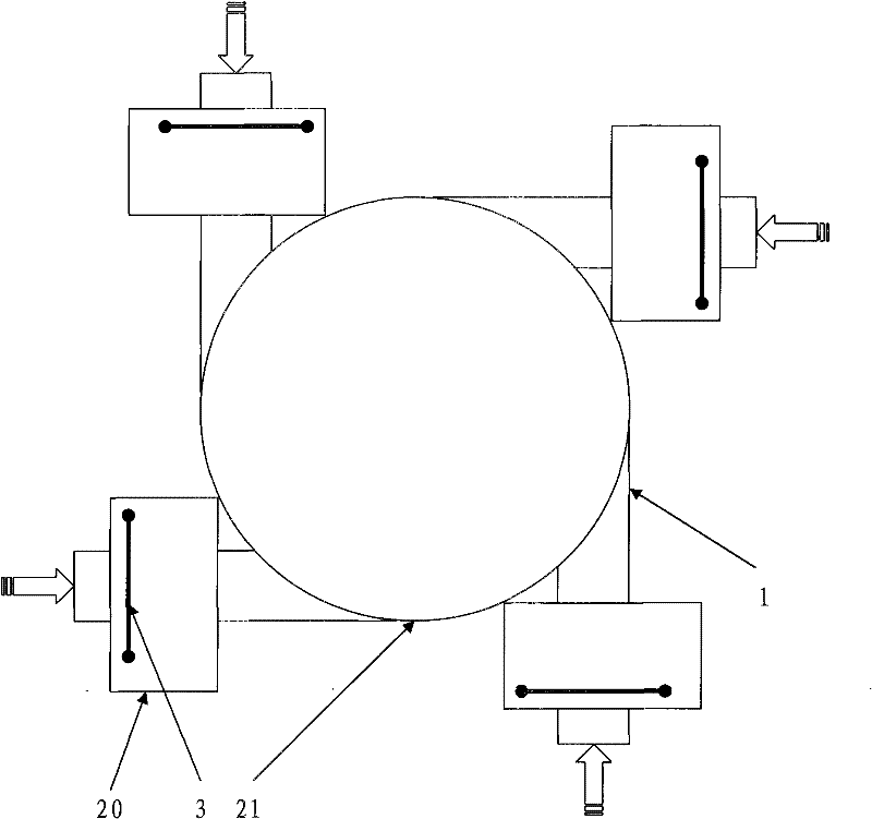
[0014] Such as figure 2 As shown, the system of the present invention is provided with a plurality of air intake branches, as shown in the figure 13, each air intake branch air inlet is equipped with a suction fan, such as label 2, to correspond to different sources of different properties The gas is extracted separately, and each induced draft fan 2 is equipped with an exhaust hood 23 . In addition, a pretreatment device 22 is provided in the air intake branch at the rear end of individual induced draft fans to pre-treat special exhaust gas, thereby improving the final exhaust gas treatment effect. E.g figure 2 In the shown embodiment, for nitric acid waste gas, a urea spray scrubber is added at the rear end of the corresponding induced draft fan to pretreat it.

[0015] The waste gas of each branch needs to be assembled and sent to the ...


PUM


Abstract

The invention relates to the waste gas treating field of electroplating industry, in particular to a waste gas treating system. The waste gas treating system comprises a gas scrubbing tower. The front end of the gas scrubbing tower is provided with a cyclone separating tower, an air inlet part of which is provided with a plurality of gas inlet pipelines, and each gas inlet pipeline is respectively provided with a suction fan and an air suction cover. By taking the air inlet part of the cyclone separating tower as a connecting part, the gas inlet pipelines are counterclockwise arranged in the circumferential tangential direction of the air inlet pipeline. The gas inlet pipeline is respectively provided with a check baffle plate. At least one gas inlet pipeline at the front end of the cyclone separating tower is provided with equipment for pretreating special waste gas. The cyclone separating tower is provided with a cooling device. The system is provided with switches for flexibly adjusting the suction fans according to the treating requirement, therefore, the operation cost can be controlled, and the waste gas of different sources and properties can be flexibly treated; the gas inlet temperature of the gas scrubbing tower is decreased, the Reynolds number is increased, the acid removing effect of the gas scrubbing tower is enhanced, the usable waste acid can be recycled, and the resources are sufficiently saved.

Description

technical field [0001] The invention relates to the technical field of exhaust gas treatment in the electroplating industry, in particular to a centralized exhaust gas treatment method and a system for exhaust gas treatment. Background technique [0002] Electroplating factories often use highly volatile hydrochloric acid, hydrofluoric acid, and nitric acid to generate acid gas and acid mist, which makes the workshop unbearably sour and smelly, which is extremely harmful to pollution prevention, industrial safety, and equipment maintenance. The industry generally uses traditional extraction scrubbers to treat waste gas (such as Figure 1 Shown), it adopts a suction scrubber tower 29, configures a suction fan 27, the suction fan leads to the gas source through the air inlet pipeline 24,26, and the air inlet end is provided with a suction hood 23, the processing equipment Certain results can indeed be received. However, there are still the following shortcomings to be solved ...

Claims


Application Information

Patent Timeline
Patent Type & Authority Patents(China)
IPC IPC(8): B01D53/78C25D21/04
Inventor 何靖
Owner 惠州益伸电子有限公司
Why Eureka
Try Eureka