Fan casing base

A technology of fan shell seat and seat body, which is applied to the components of pumping devices for elastic fluids, non-variable-capacity pumps, machines/engines, etc. Air volume etc.

Inactive Publication Date: 2010-08-04
SUNON ELECTRONICS KUNSHAN
View PDF1 Cites 2 Cited by
  • Summary
  • Abstract
  • Description
  • Claims
  • Application Information

AI Technical Summary

Problems solved by technology

[0003] Generally speaking, in order to maintain the overall fan air output and reduce the noise of the existing blower fan, the blower fan should be minimized in the air outlet area near the air outlet 914 of the shell base 91 (ie figure 2 The support rib 913 or other fan components are arranged in the region of the side of the middle dividing line a near the air outlet 914 to avoid the occurrence of turbulent flow; only the aforementioned existing blower fan is provided with the three There are three ventilation holes 911 to improve the overall air intake, but it is unavoidable to form at least one complete supporting rib 913 in the air outlet area, so that the gas is easily interfered by the support rib 913 when passing through the air outlet area to form a turbulent flow. As a result, the overall air volume of the existing blower fan is reduced, and the overall noise level is also increased, so it is necessary to improve

Method used


Image

  • Fan casing base
  • Fan casing base
  • Fan casing base

Examples


Embodiment Construction

[0027] In order to make the above-mentioned and other objects, features and advantages of the present invention more comprehensible, the preferred embodiments of the present invention are specifically cited below, together with the accompanying drawings, as follows:

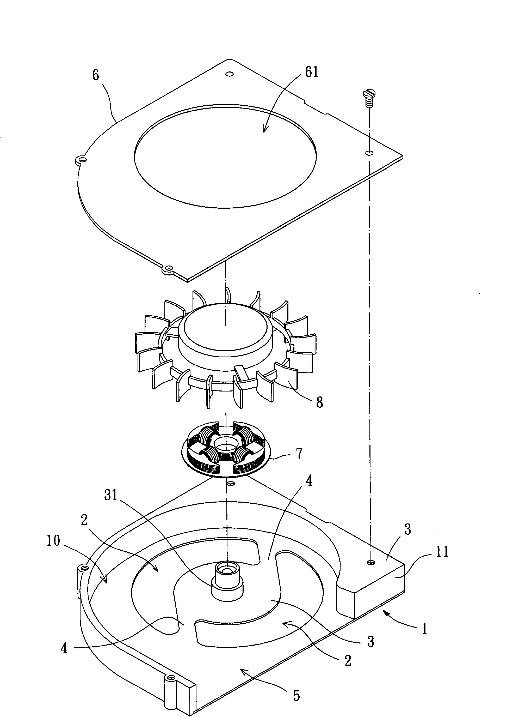
[0028] Please refer to image 3 As shown, what the fan case seat of the present invention selects under the present implementation state is the case seat of a two-way air blowing fan, and the fan case seat is a seat body 1 with a top opening, two air holes 2, an assembly part 3, Two supporting ribs 4, an air outlet 5 and a cover plate 6, the base body 1 has an accommodating space 10 and a side wall portion 11, the accommodating space 10 is formed between the side wall portions 11, and the drum A stator 7 and a fan wheel 8 of the fan are installed in the accommodating space 10; the cover plate 6 is aligned and assembled on the top opening of the base body 1, and the cover plate 6 is provided with an air inlet 61, ...


PUM


Abstract

The invention relates to a fan casing base which comprises a base body, two ventilation holes, an assembling part, two support ribs and an air outlet. The two ventilation holes and the assembling part are respectively arranged at the bottom of the base body, and the assembling part is positioned between the two ventilation holes. The two support ribs are formed at the position adjacent to the two ventilation holes, and both ends of the two support ribs are respectively connected with the bottom of the base body and the assembling part. The air outlet is arranged on the side wall of the base body. The base body is separated into an air outlet zone and an air storing zone by taking one separation line as the boundary. The air outlet zone is the area of the base body adjacent to the air outlet, and the air storing zone is the other area. The air outlet zone is not provided with any complete support rib, thereby avoiding forming turbulent flow in the air outlet zone.

Description

technical field [0001] The invention relates to a fan casing, in particular to a blower fan casing with vents. Background technique [0002] Existing blower fan casing, such as the invention patent case of "SmallHeat-Dissipating Device, miniature cooling device" of US Patent Publication No. 20070222331. Please refer to figure 1 As shown, the conventional blower fan 9 generally includes a casing 91 , a stator 92 and a fan wheel 93 . The housing base 91 is a base with an opening at the top, which has an accommodating space; the bottom of the housing base 91 is provided with three ventilation holes 911, and the three ventilation holes 911 are aligned under the fan wheel 93 to form a ring shape. Arrangement; the shell base 91 is provided with an assembly part 912 between the three vent holes 911, the assembly part 912 is connected to the bottom of the shell base 91 via three support ribs 913, and each support rib 913 is located at each of the Between the air holes 911; the st...

Claims


Application Information

Patent Timeline
Patent Type & Authority Applications(China)
IPC IPC(8): F04D29/40
Inventor 洪银树
Owner SUNON ELECTRONICS KUNSHAN
Why Eureka
Try Eureka