
Two-layer distribution method and base station

An allocation method and base station technology, applied in the direction of preventing/detecting errors through diversity reception, digital transmission systems, electrical components, etc., can solve problems such as limited transmission performance, and achieve the effect of ensuring system performance and optimizing signaling overhead.

Active Publication Date: 2010-08-04
ZTE CORP
View PDF1 Cites 6 Cited by
  • Summary
  • Abstract
  • Description
  • Claims
  • Application Information

AI Technical Summary

Problems solved by technology

In addition, due to the limitation of transmission performance, during multi-user transmission, a user can allocate up to two layers of resources; when the total number of transmission layers or the rank is greater than 2, there is currently no plan how to allocate two layers to the target user

Method used


Image

  • Two-layer distribution method and base station
  • Two-layer distribution method and base station

Examples

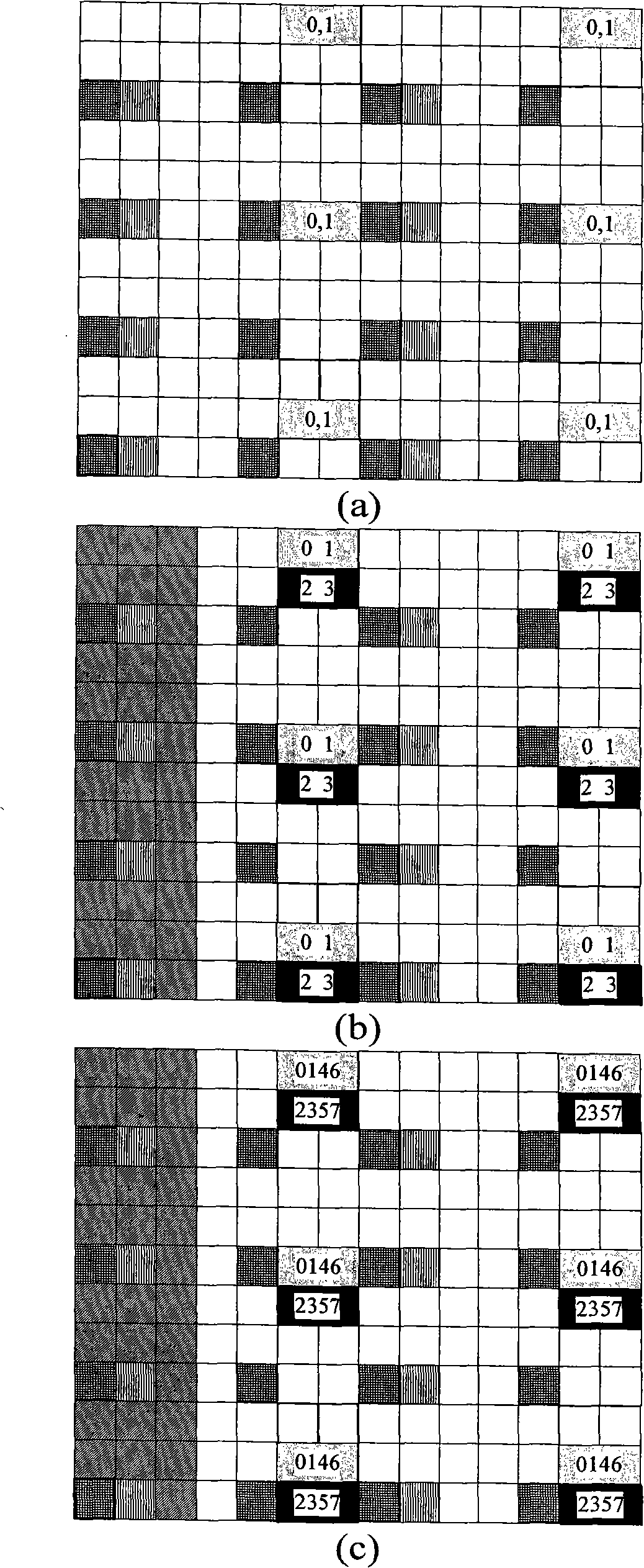

Embodiment Construction

[0025] Considering the problem that the demodulation pilot-based MIMO multi-user transmission is not supported in LTE version 10 in the related art, the present invention provides a two-layer allocation method, which provides a user with two layers during multi-user transmission. The possibility of layer transmission, by assigning layer restrictions, optimizes the overhead of signaling to the greatest extent on the premise of ensuring system performance.

[0026] Assume that the pilot patterns corresponding to the first layer and the second layer are the first pilot pattern, the pilot patterns corresponding to the third layer and the fourth layer are the second pilot pattern, and the pilot patterns corresponding to the fifth layer, the sixth layer, the seventh layer and the eighth layer are The frequency pattern is the third pilot pattern.

[0027] The two-layer allocation method provided by the present invention includes: the total number of layers or the rank of the current ...


PUM


Abstract

The invention provides a two-layer distribution method. The method comprises the following steps: dividing the total current transmission layers into a plurality of groups, wherein each group corresponds to one layer or two layers, and the layers corresponding to each group are different; and when the data of a target user is transmitted on two layers, distributing the group, corresponding to the two layers, of the multiple groups to the target user. The invention also provides a base station. The invention realizes the possibility of two layer transmission of a user during multi-user transmission, and optimizes signalling expenditure to the utmost extent on the premise of ensuring the system performance by distribution limitation on two layer users.

Description

technical field [0001] The invention relates to the field of mobile communication, in particular to a two-layer distribution method and a base station. Background technique [0002] In wireless communication, if multiple antennas are used at the sending end (such as an evolved base station (eNB)), spatial multiplexing can be adopted to increase the transmission rate, that is, transmitting at different antenna positions on the same time-frequency resource at the sending end For different data, multiple antennas are also used at the receiving end (UE), and the resources of all antennas can be allocated to the same user in the case of a single user. This transmission form is called SU-MIMO (Single User Multiple Input Multiple Output). In addition, resources in different antenna spaces can also be allocated to different users in the case of multiple users. This transmission form is called MU-MIMO (Multi-User MIMO). If the transmission system is to support single-user MIMO and m...

Claims


Application Information

Patent Timeline
Patent Type & Authority Applications(China)
IPC IPC(8): H04L5/02H04L1/06
CPCH04L5/0023
Inventor 戴博李儒岳孙云锋郁光辉张峻峰
Owner ZTE CORP
Learn More