Device and bead pipe adding on common embroidery machine for arranging bead pipe direction
An embroidery machine and bead tube technology, applied in the field of bead tube machine embroidery equipment, can solve the problems of low efficiency, random direction, low quality, etc., and achieve the effect of increasing the falling speed and ensuring the requirements of embroidery.
- Summary
- Abstract
- Description
- Claims
- Application Information
AI Technical Summary
Problems solved by technology
Method used
Image
Examples
Embodiment 1
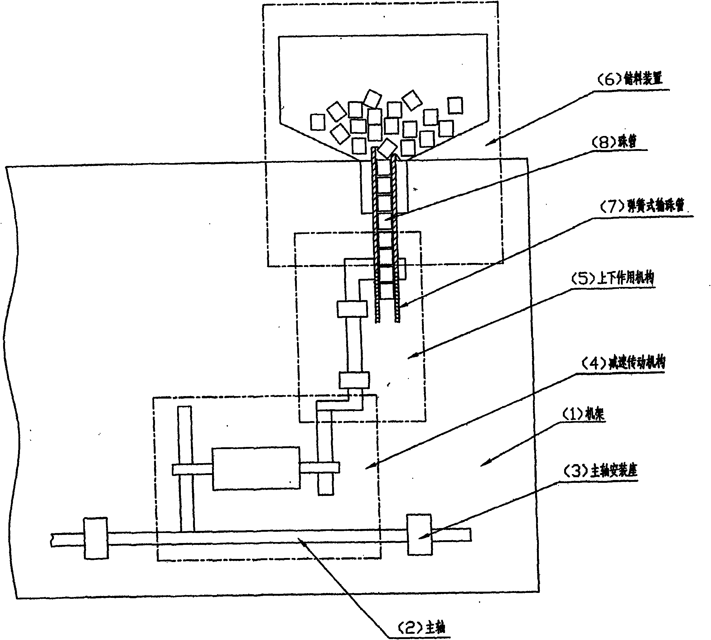
[0016] Embodiment 1: as figure 1 As shown, the ordinary embroidery machine is equipped with a device for arranging the direction of the bead tube and the bead tube, which includes: a frame 1, a main shaft 2, a main shaft press seat 3, a reduction transmission mechanism 4, an up and down action mechanism 5, a material storage device 6, The spring-type bead pipe 7, the bead pipe 8, the main shaft 2 are installed on the frame 1 through the main shaft mounting seat 3, the reduction transmission mechanism 4, the up and down action mechanism 5 and the material storage device 6 are all installed on the frame 1, The deceleration transmission mechanism 4 coincides with the main shaft 2, the upper and lower action mechanism 5 communicates with the deceleration transmission mechanism 4, the material storage device 6 is connected with the upper and lower action mechanism 5, the spring type bead delivery tube 7 is connected with the material storage device 6, and the bead tube 8 is placed i...
Embodiment 2
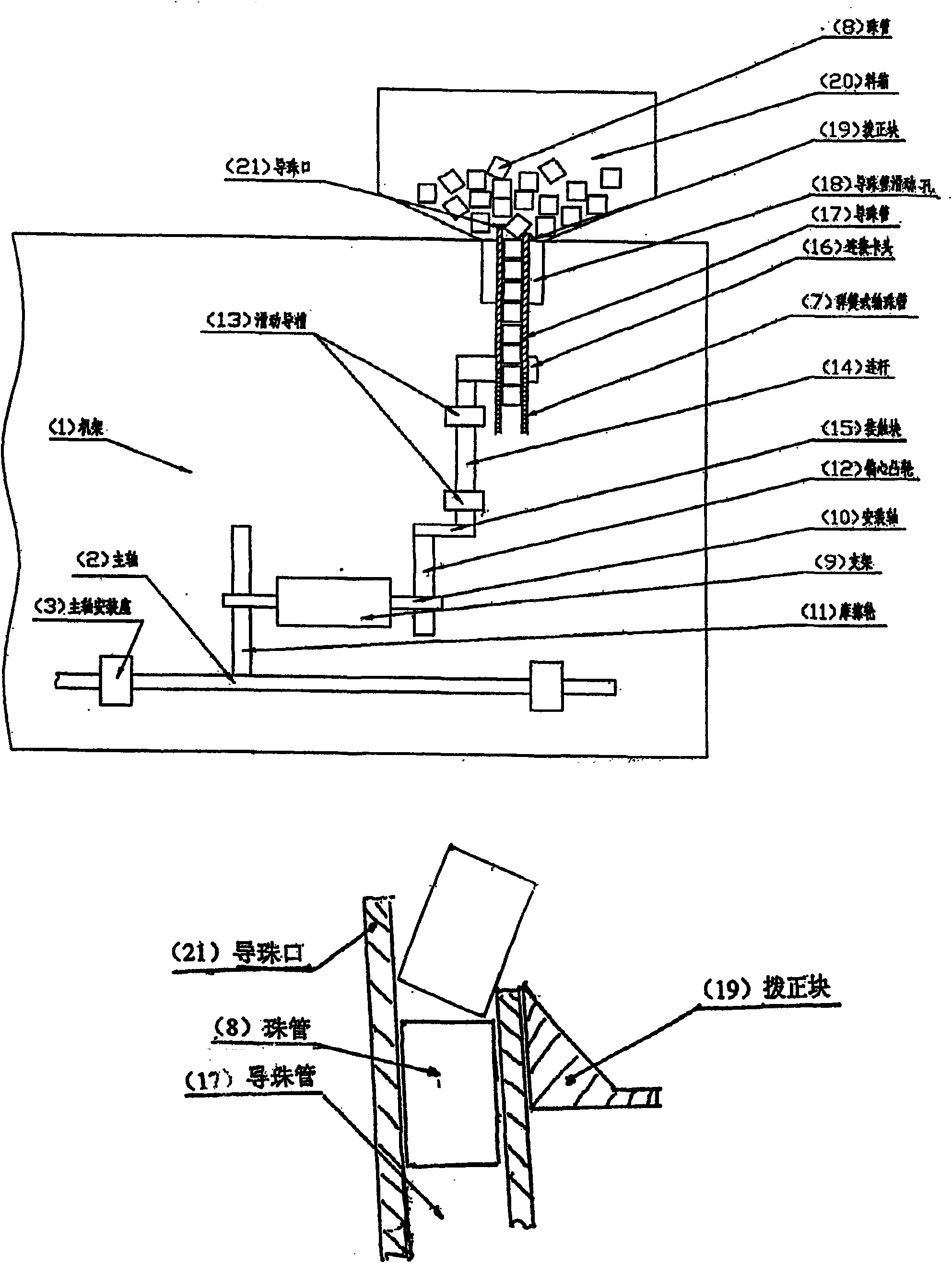
[0017] Embodiment 2: as figure 1 and figure 2 As shown, the device for adjusting the direction of the bead tube and the structural diagram of the various mechanisms of the bead tube and the cross-sectional view of the guide bead tube and the straightening block are installed on the ordinary embroidery machine. It includes: a bracket 9, a mounting shaft 10, and a friction wheel 11 , eccentric cam 12, sliding guide groove 13, connecting rod 14, the bottom of connecting rod 14 is provided with contact block 15, the upper part is provided with connecting chuck 16, guide bead tube 17, guide bead tube sliding hole 18, set right block 19 and material Box 20, bracket 9 is fixed on the frame 1, the mounting shaft 10 is mounted in the bracket 9, the friction wheel 11 is fixed on the mounting shaft 10 and coincides with the main shaft 2, and the eccentric cam 12 is fixed on the mounting shaft 10; The sliding guide groove 13 is installed on the frame 1, the connecting rod 14 is placed i...
PUM
| Property | Measurement | Unit |
|---|---|---|
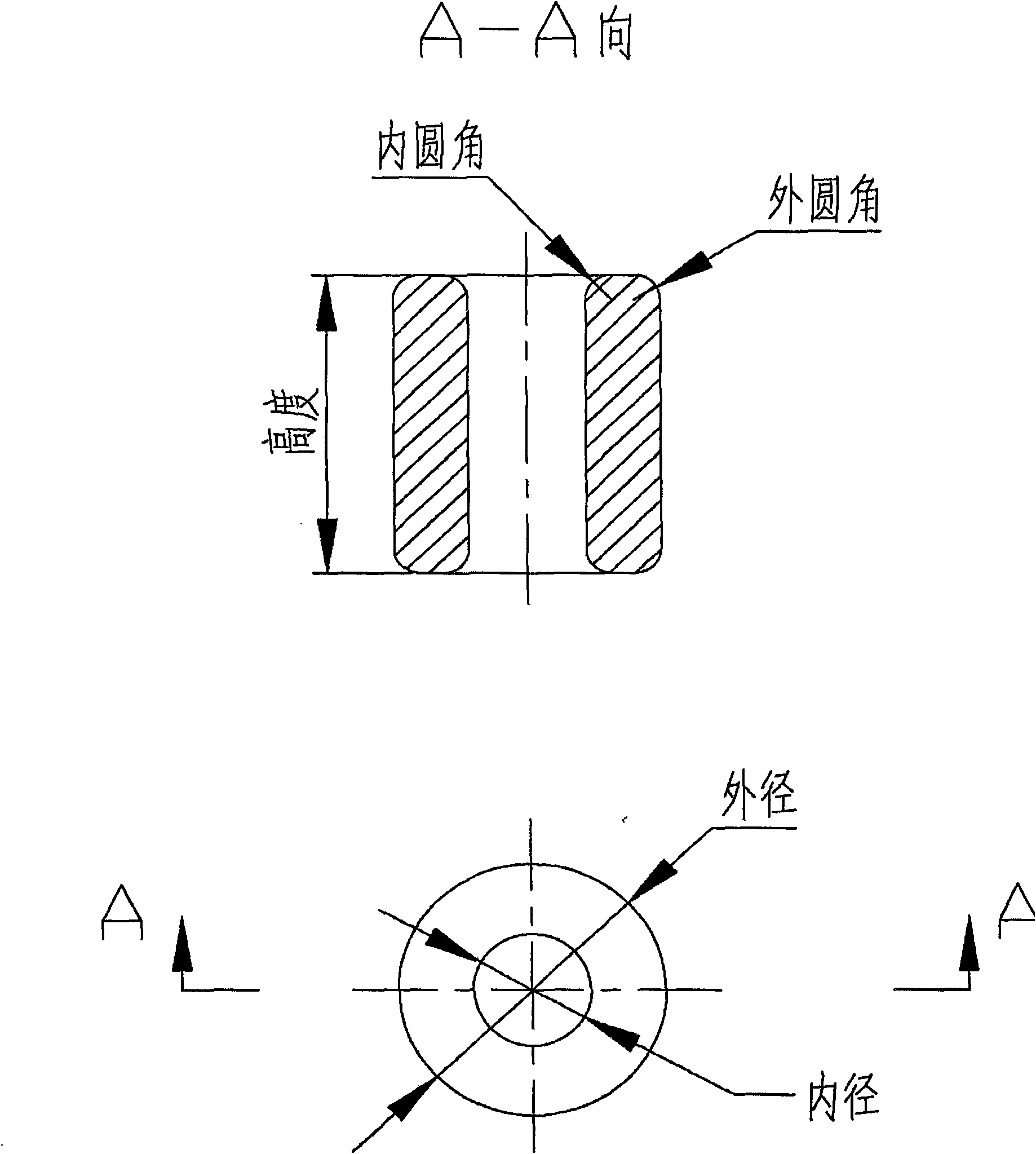
| Inner diameter size | aaaaa | aaaaa |
| Height dimension | aaaaa | aaaaa |
| Diameter size | aaaaa | aaaaa |
Abstract
Description
Claims
Application Information
 - R&D
- Intellectual Property
- Life Sciences
- Materials
- Tech Scout
- Unparalleled Data Quality
- Higher Quality Content
- 60% Fewer Hallucinations
Browse by: Latest US Patents, China's latest patents, Technical Efficacy Thesaurus, Application Domain, Technology Topic, Popular Technical Reports.
© 2025 PatSnap. All rights reserved.Legal|Privacy policy|Modern Slavery Act Transparency Statement|Sitemap|About US| Contact US: help@patsnap.com


