
Aiming arm for locking of bone nails

A technology of bone and aligning part, applied in the direction of fixator, internal fixator, bone drill guidance, etc., can solve problems such as difficulties, achieve the effect of simple and fast fixation, and reduce X-ray exposure

Inactive Publication Date: 2010-08-11
SYNTHES GMBH
View PDF6 Cites 5 Cited by
  • Summary
  • Abstract
  • Description
  • Claims
  • Application Information

AI Technical Summary

Problems solved by technology

However, learning to use this device has proven difficult

Method used


Image

  • Aiming arm for locking of bone nails
  • Aiming arm for locking of bone nails
  • Aiming arm for locking of bone nails

Examples


Embodiment approach

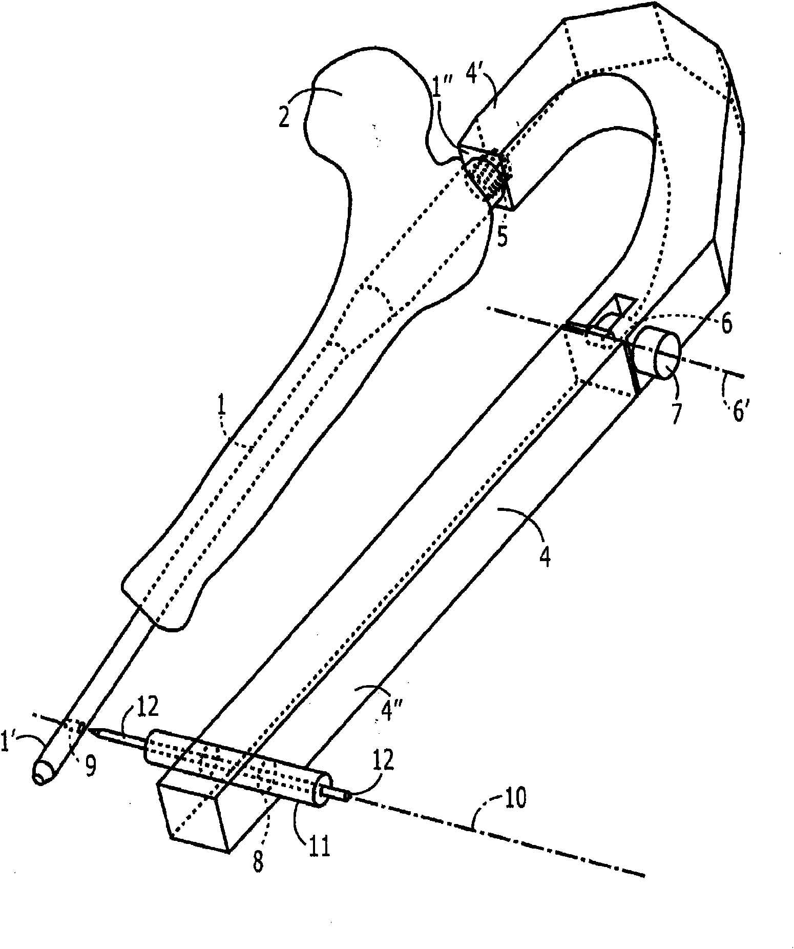
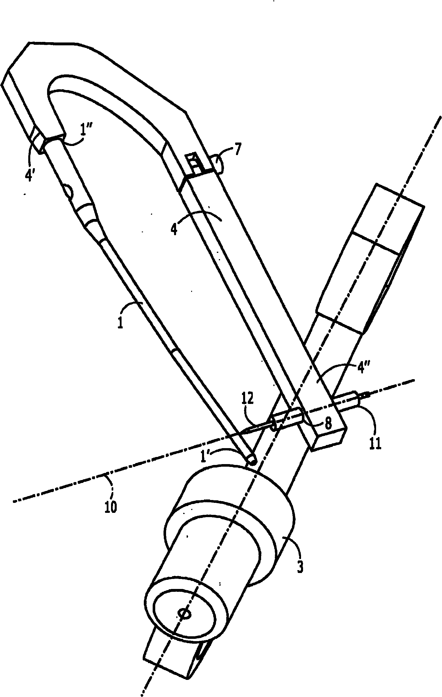
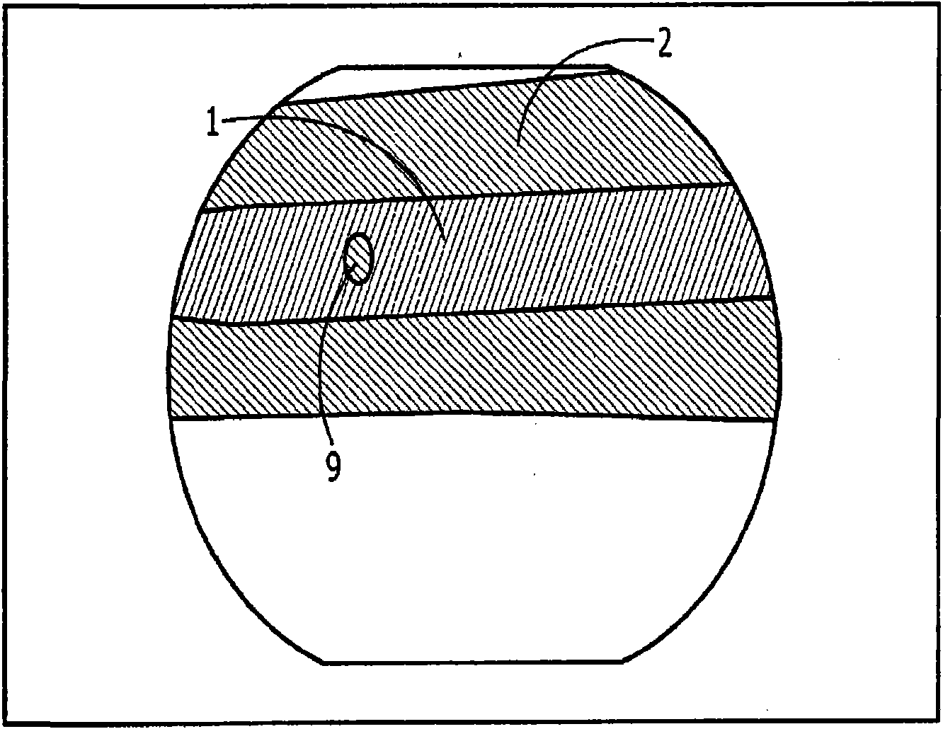
[0028] Such as figure 2As shown, the aiming arm 4 is connected to the nail 1 for example in an orientation which places the axis of the hole 8 in alignment with the axis 10 of the hole 9 of the nail 1 . For example, prior to insertion into the body, the aiming arm 4 can be coupled to the nail 1 and the orientation of the proximal portion 4″ relative to the distal portion 4′ can be adjusted until the axes of the holes 8 and 9 are perfectly aligned with each other. Then through The relative positions of the proximal portion 4″ and the distal portion 4′ of the aiming arm 4 are respectively locked using the knob 7 so that the aiming arm 4 can be removed from the nail 1 during insertion if desired without changing the hole 8. Reattach the aiming arm 4 without the alignment of the and 9 axes. However, deformation of the nail 1 during insertion into the femur 2 (not shown in this figure) displaces the hole 9 and misaligns the axis 10 with the hole 8, as described below. With the p...


PUM


Abstract

An aiming arm (4) comprises a rigid distal member a distal portion (4') of which is configured to be releasably coupled to a proximal end (1' ') of an implant (1) to be implanted in a medullary canal of a bone (2), so that, when coupled to the proximal end of an implant, an orientation of the proximal end of the implant relative to the distal portion of the aiming arm remains constant in combination with a rigid proximal member (4'') a distal portion of which is rotatably coupled to a proximal end of the distal member. The proximal member includes an aligning feature (8) defining an axis. (10) aligned with an axis of a fixation element receiving hole (9) extending through a distal portion of the implant, the proximal member being rotatable after implantation of the implant, to an adjustedconfiguration in which the aligning feature is aligned with a post-implantation orientation of the fixation element.

Description

Background technique [0001] Bone screws, such as intramedullary nails, typically lock in two positions - a first position near the point of entry and a second position distal from the point of entry. The end of the nail that is inserted into the bone and penetrates the deepest from the entry site is called the distal end, while the end of the nail that remains close to the entry site is called the proximal end. As used in this application, the term "distal" refers to a direction away from the point of insertion of the intramedullary implant (i.e., the front end that is first inserted into the bone is the distal end, regardless of the end of the bone into which this front end is inserted). what), while the term "proximal" refers to the opposite direction. Locking of such nails is currently achieved through the use of mechanical aiming devices (eg, aiming arms) or X-ray guides. [0002] A mechanical aiming device as disclosed in US Patent No. 6,514,253 is generally removably a...

Claims


Application Information

Patent Timeline
Patent Type & Authority Applications(China)
IPC IPC(8): A61B17/17
CPCA61B17/1725A61B17/1703A61B2017/1778A61B17/72A61B17/1778
Inventor 阿尔贝托·A·戴尔欧卡费尔南德斯马尔库斯·布特勒
Owner SYNTHES GMBH
Learn More