

Valve gear for internal combustion engine
A technology for internal combustion engines and valves, applied to valve devices, mechanical equipment, engine components, etc., can solve the problem of a large number of parts and achieve the effect of changing the valve opening characteristics
- Summary
- Abstract
- Description
- Claims
- Application Information
AI Technical Summary
Problems solved by technology
Method used
Image

Examples
Embodiment 1
[0069] first refer to Figure 1 to Figure 11 Embodiment 1 of the present invention will be described.
[0070] 〔Overall structure of the valve gear〕
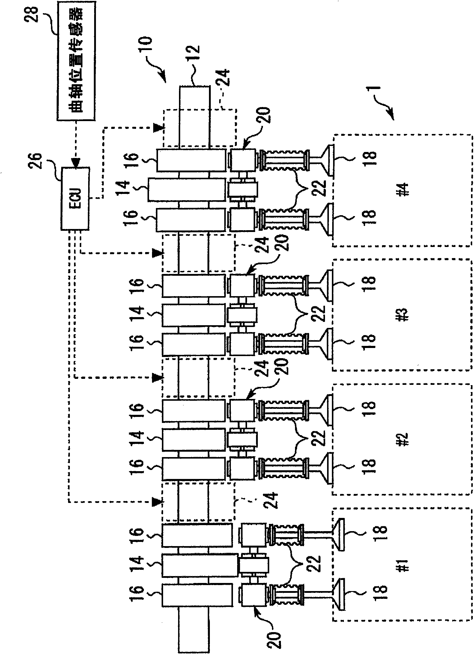
[0071] figure 1 It is a view schematically showing the overall structure of the valve device 10 of the internal combustion engine 1 according to Embodiment 1 of the present invention.
[0072] Here, the internal combustion engine 1 has four cylinders (#1 to #4), and is an inline four-cylinder engine that performs a combustion expansion process in the order of #1→#3→#4→#2. Furthermore, each cylinder of the internal combustion engine 1 has two intake valves and two exhaust valves. and, figure 1 The shown structure functions as a mechanism for driving two intake valves or two exhaust valves provided in each cylinder.
[0073] The valve device 10 of the present embodiment has a camshaft 12 . The camshaft 12 is connected to a crankshaft (not shown) through a timing chain or a timing belt, and rotates at 1 / 2 the crankshaft speed...
Embodiment 2
[0155] Next, refer to Figure 12 Example 2 of the present invention will be described.
[0156] The structure of the valve device 10 of the present embodiment is the same as that described above except for the setting of the helical groove 80 provided on the large-diameter portion 62 of the camshaft 12. Figure 7 Except for the difference in the setting of the helical groove 64 shown, it has the same structure as the valve device 10 of the first embodiment described above.
[0157] Figure 12 It is a developed view for explaining the setting of the helical groove 80 in Embodiment 2 of the present invention.
[0158] In above-mentioned embodiment 1, with above-mentioned Figure 7 In the illustrated form, the helical groove 64 is set so that most of the shallow groove portion 64c of the helical groove 64 gradually becomes shallower from the end 64b side is located in the lift section. Also, the timing E, that is, the timing at which the function of the retaining slide pin 58...
Embodiment 3
[0163] Next, refer to Figure 13 and Figure 14 , Embodiment 3 of the present invention will be described.
[0164] The structure of the valve device 10 of this embodiment is the same as that of the valve device 10 of the first embodiment except for the difference in the structure of the joint portion between the notch portion 90 e of the slide pin 90 and the lock pin 92 .
[0165] Figure 13 is an enlarged view of the bonding portion in Embodiment 1, which is used for comparison with the structure of Embodiment 3 of the present invention.
[0166] exist Figure 13 In the shown structure, the inner surface of the notch part 58e of the slide pin 58 and the peripheral surface of the lock pin 70 which consists of a single diameter are joined. This combination requires two properties. That is, the first performance is the performance of receiving and holding the slide pin 58 against the urging force of the return spring 56 , and the second performance is a good response perfo...
PUM
 Abstract
Description
Claims
Application Information