Knitting design device, kintting design method and kintting design program

A technology for knitted fabrics and needle beds, applied in the field of knitted fabric design, can solve the problems of displaying knitted fabrics, difficulties, etc.

Active Publication Date: 2010-08-11
SHIMA SEIKI MFG LTD
View PDF1 Cites 4 Cited by
  • Summary
  • Abstract
  • Description
  • Claims
  • Application Information

AI Technical Summary

Problems solved by technology

However, it is difficult to simulate at high speed, so it is difficult to display the desired part of the knitted fabric on the monitor in real time

Method used


Image

  • Knitting design device, kintting design method and kintting design program
  • Knitting design device, kintting design method and kintting design program
  • Knitting design device, kintting design method and kintting design program

Examples


Embodiment

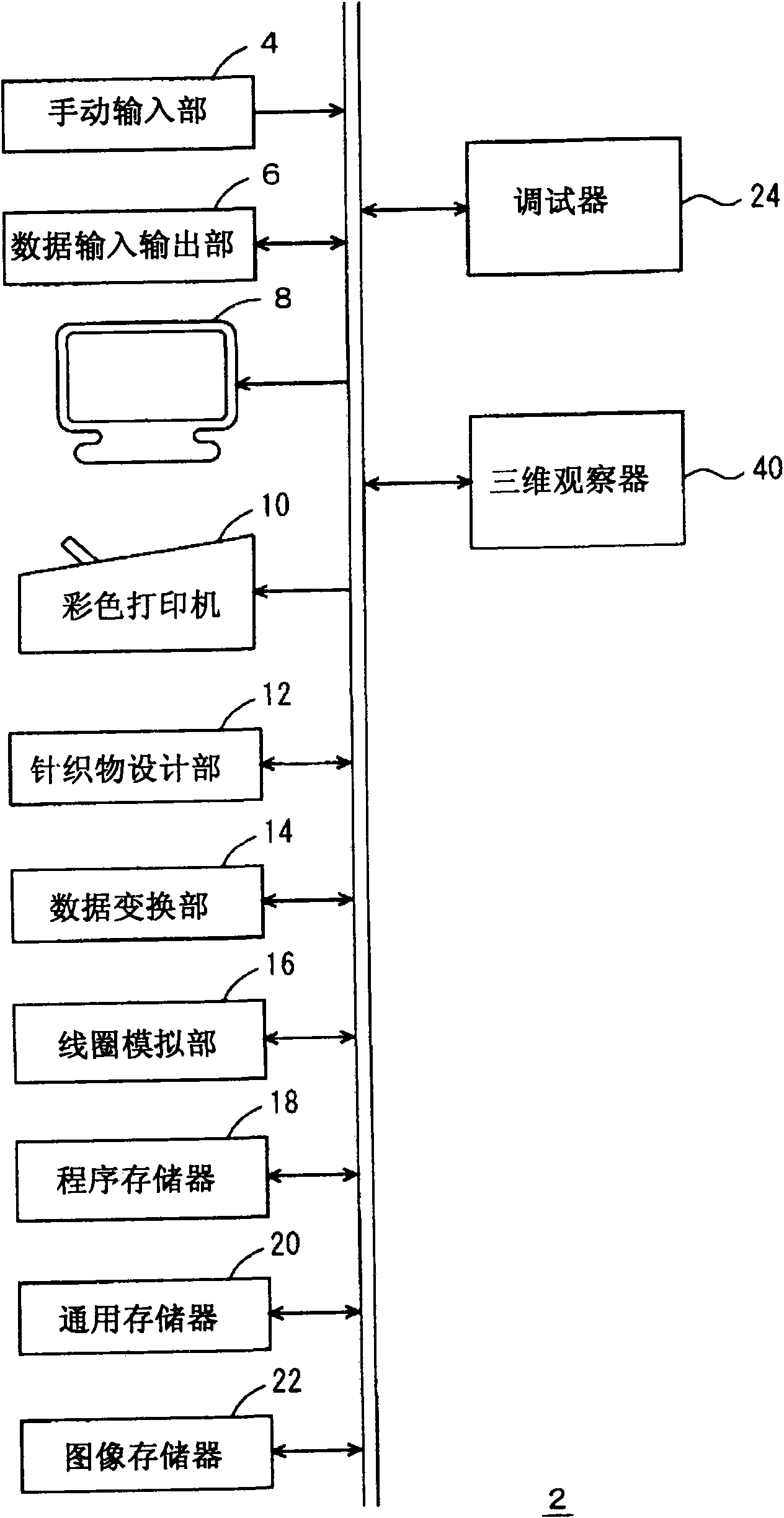
[0091] Figure 1 to Figure 13 Indicates an example. exist figure 1 Among them, 2 is a knitted fabric design device, and 4 is a manual input unit, which is a keyboard, a stylus, a mouse, a track ball, a joystick, and the like. The data input / output unit 6 inputs and outputs various data, and is composed of a disk drive, a network interface, and the like. The color monitor 8 and the color printer 10 output various data such as design data of knitted products, simulation data of completed knitted products, and images of a three-dimensional viewer described below.

[0092] The knitted fabric design unit 12 designs knitted products based on inputs from the data input and output unit 6 and the manual input unit 4 . Then, the obtained design data is converted by the data conversion unit 14 into knitting data that can be knitted by the flat knitting machine. The stitch simulation 16 generates an image of a simulated knitted fabric to display each stitch based on the knitting data....


PUM


Abstract

Stitch arrangement data are divided into a plurality of blocks. Among stitches in a block the center of which belongs to a display area and stitches in blocks adjacent to this block, stitches are extracted in a part where a line connecting the starting point and the front edge of the stitches runs against the display area. With these stitches taken as display subjects, a 3-D image corresponding to a viewing direction is made out. This can provide a 3-D simulation image of a weaving ground for necessary points on a real time basis.

Description

technical field [0001] The present invention relates to knitted fabric design, in particular to the technology of displaying knitted fabric design locally in real time. Background technique [0002] Patent Document 1 (Japanese Patent No. 2678228) discloses a technique of designing a knitted product using a knitted fabric design device composed of a computer, converting the design result into knitting data, and displaying a simulated image of the knitted fabric knitted based on the knitting data. However, it is difficult to simulate at high speed, so it is difficult to display the desired site of the knitted fabric on the monitor in real time. [0003] Patent Document 1: Japanese Patent No. 2678228 Contents of the invention [0004] An object of the present invention is to display a simulated image of a design of a knit product in real time. [0005] A sub-objective of the present invention is to display not only the image of the knitted fabric viewed from the front, but ...

Claims


Application Information

Patent Timeline
Patent Type & Authority Applications(China)
IPC IPC(8): G06F17/50D04B35/00
CPCG06F17/5009G06T19/00G06T2210/16G06F2217/32D04B37/02G06F30/20G06F2113/12
Inventor 寺井公一
Owner SHIMA SEIKI MFG LTD
Why Eureka
Try Eureka