
Manufacturing process of MD and RB integrated forming die

A molding mold and manufacturing process technology, which is applied in the field of MD and RB integral molding mold manufacturing technology, can solve the problems of high mold quality defect rate, steam/cooling water leakage, low heat conduction/cooling coefficient of stainless steel pipe, etc., to improve heat conduction And the effect of cooling affected area, process difficulty and defect rate reduction, labor cost and dependence reduction

Inactive Publication Date: 2019-05-24
泉州鸿展模具制造有限公司
View PDF3 Cites 0 Cited by
  • Summary
  • Abstract
  • Description
  • Claims
  • Application Information

AI Technical Summary

Problems solved by technology

[0003] 1. The traditional MD forming mold mainly adopts upper and lower casting. When the sole is formed, the sulfuration and cooling time of the mold are long, the product rate is low, and the energy consumption is high.
[0004] 2. The cooling water channel in the mold is made of stainless steel pipe embedded in the mold for casting. The stainless steel pipe has a low thermal conductivity / cooling coefficient, and looseness between the pipe and the mold is easy to occur. Therefore, the sulfur addition and cooling time in the production process is long, and the energy consumption is high. High, and during the production process of the mold, the stainless steel pipe is easy to oxidize and rust, and there will be water / steam leakage
[0005] 3. The cooling water channel in the mold adopts a sand core casting mold, which has a high defect rate. Since the cooling water channel needs to design the channel size according to the thickness and height of the product, it is necessary to adopt a curved design at the turning point to make a sand core setting mold It is difficult to form and easy to break, and it is extremely difficult to take out the sand core after the mold is cast, which takes a long time and has a high scrap rate in mold making; the cooling water channel is formed by integral casting with the sand core and the mold, and sand holes or shrinkage cavities often appear, resulting in Leakage of steam / cooling water, high defect rate of mold quality
[0006] 4. In addition, the cooling water channel adopts pipe casting or sand core molding, and the channels are of uniform size, and the thickness of the keel before and after the finished sole is about 10MM, and because the vulcanization time of the finished shoe sole is the same, the vulcanization of the thick part of the keel is OK. , The thin part of the finished keel is overcooked, which affects the physical properties of the finished shoe sole

Method used


Image

  • Manufacturing process of MD and RB integrated forming die
  • Manufacturing process of MD and RB integrated forming die
  • Manufacturing process of MD and RB integrated forming die

Examples


Embodiment 1

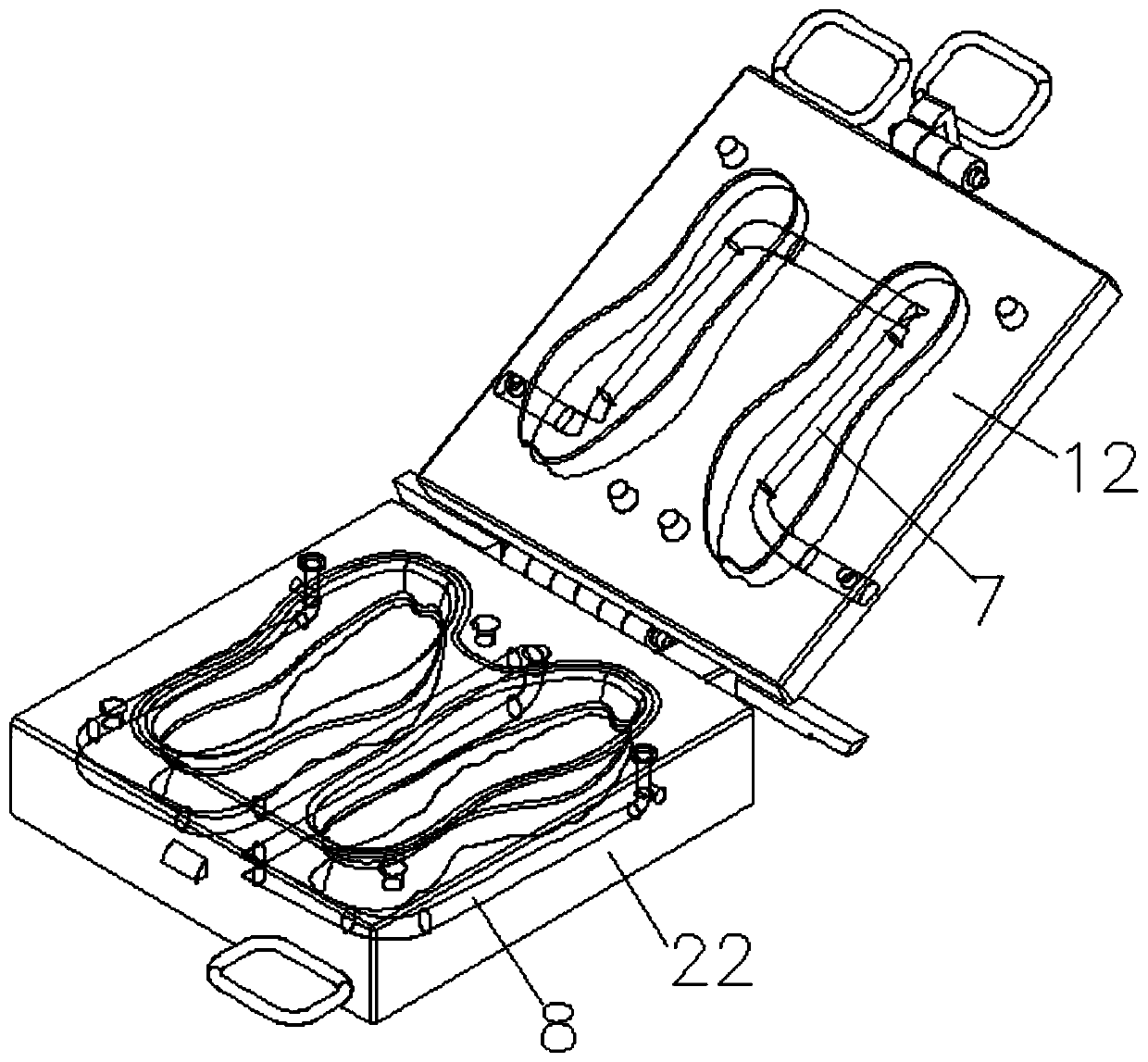
[0043] Refer to as Figure 1 to Figure 8 Shown, a kind of MD of the present embodiment, the manufacturing process of RB integral mold, it comprises the following steps:

[0044] A. Make a loop through channel model:

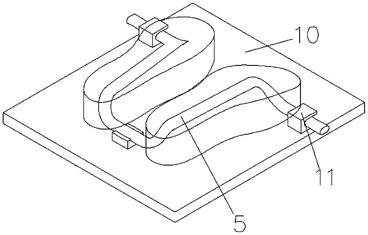
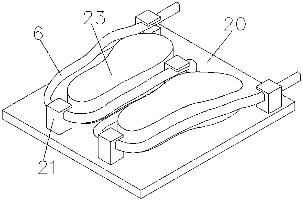
[0045] (1) According to the thickness of the finished shoe sole and the shape of the circulation channel, through 3D printing the required channel simulation model, the channel simulation model includes the upper mold channel simulation model and the lower mold channel simulation model;

[0046] (2) Production of the simulation model of the upper mold channel: the surrounding of the upper mold channel simulation model is compounded with a certain thickness of silica gel, the upper mold channel simulation model is wrapped in the interior of the silica gel, and the thickness of the silica gel is cut along the center line into two pieces of silica gel , take out the channel simulation model in each piece of silica gel, make the corresponding surfaces of the two pie...

Embodiment 2

[0056] A kind of manufacturing technology of MD, RB integral molding mold, it comprises the steps:

[0057] A. Make a loop through channel model:

[0058] (1) According to the thickness of the finished shoe sole and the shape of the circulation channel, through 3D printing the required channel simulation model, the channel simulation model includes the upper mold channel simulation model and the lower mold channel simulation model;

[0059] (2) Production of the simulation model of the upper mold channel: the surrounding of the upper mold channel simulation model is compounded with a certain thickness of silica gel, the upper mold channel simulation model is wrapped in the interior of the silica gel, and the thickness of the silica gel is cut along the center line into two pieces of silica gel , take out the channel simulation model in each piece of silica gel, make the corresponding surfaces of the two pieces of silica gel form the channel model grooves of the upper mold, and...


PUM


Abstract

The invention discloses a manufacturing process of an MD and RB integrated forming die. The manufacturing process of the MD and RB integrated forming die comprises the following steps of A, making a circulating through channel model; and B, making a die to form. The MD and RB integrated forming die is mainly used for producing secondary EVA and secondary EVA and a large bottom RB integrally formedproduct; the die material is an aluminum die; and the circulating channel and the aluminum die are integrally formed, and the heat conduction and the cooling are fast; the circulating channel can bemanufactured according to the thickness of the product and the 3D analog mathematical analysis of the height of the side wall, the production of the product is directly influenced by steam and water,the production period is shortened, the productivity is improved, and the energy consumption is reduced; the die is provided with a vacuumizing mechanism, so that the secondary MD fine pattern can beformed well, a bottle ballast with the appearance that the appearance of the secondary MD fine pattern cannot be molded is coated, the die is produced by an automatic machine, and manual operation isreduced.

Description

technical field [0001] The invention relates to a manufacturing method of a mould, in particular to a manufacturing process of an MD and RB integral molding mould. Background technique [0002] The shoe sole mold is mainly used for complete injection of raw materials. There is a circulation passage in the mold. The cooling water circulates and cools in the circulation passage, and finally uses the raw materials in the mold to cool and form. The production of the existing mold mainly includes the following processes and defects: [0003] 1. The traditional MD forming mold mainly adopts upper and lower casting. When the sole is formed, the sulfuration and cooling time of the mold are long, the product rate is low, and the energy consumption is high. [0004] 2. The cooling water channel in the mold is made of stainless steel pipe embedded in the mold for casting. The stainless steel pipe has a low thermal conductivity / cooling coefficient, and looseness between the pipe and th...

Claims


Application Information

Patent Timeline
IPC IPC(8): B29C33/38
Inventor 邱绍恒尹艳军
Owner 泉州鸿展模具制造有限公司
Learn More