System and method for high-speed laser detection of ultrasound

a laser detection and ultrasound technology, applied in the field of laser light amplification system and method, can solve the problems of multimode operation, affecting the detection accuracy of ultrasound, so as to minimize the optically-induced thermal heating of the laser medium, extend the dynamic range of detection, and maximize the pulse rate

Inactive Publication Date: 2007-10-23
LOCKHEED MARTIN CORP
View PDF59 Cites 13 Cited by
  • Summary
  • Abstract
  • Description
  • Claims
  • Application Information

AI Technical Summary

Benefits of technology

[0020]The present invention generates an amplified and pulsed laser beam which possesses similar physical properties of the original seed laser including a desired center frequency and linewidth for use within an optical interferometer to perform ultrasonic detection. Additionally, the output intensity of the pulsed, amplified laser beam may be modulated to extend the dynamic range of detection within an optical interferometric system. Electro-optic modulators comprising Pockels or Kerr effect crystals provide intensity modulation of a laser beam.
[0021]The present invention may perform optical pumping of a high-gain laser medium using a pumping array of laser diodes. This method permits optical pumping within a very narrow wavelength regime selected by the use of appropriate laser diodes to minimize optically-induced thermal heating of the laser medium. This advantage is provided primarily by the fact that the appropriate choice of laser diodes which comprise the pumping array may be chosen to optically pump withi

Problems solved by technology

Undesirable parasitic feedback may corrupt the seed laser source resulting in deleterious performance of the seed laser including am

Method used


Image

  • System and method for high-speed laser detection of ultrasound
  • System and method for high-speed laser detection of ultrasound
  • System and method for high-speed laser detection of ultrasound

Examples


Embodiment Construction

[0039]Embodiments of the present invention are illustrated in the FIGUREs, like numerals being used to refer to like and corresponding parts of the various drawings.

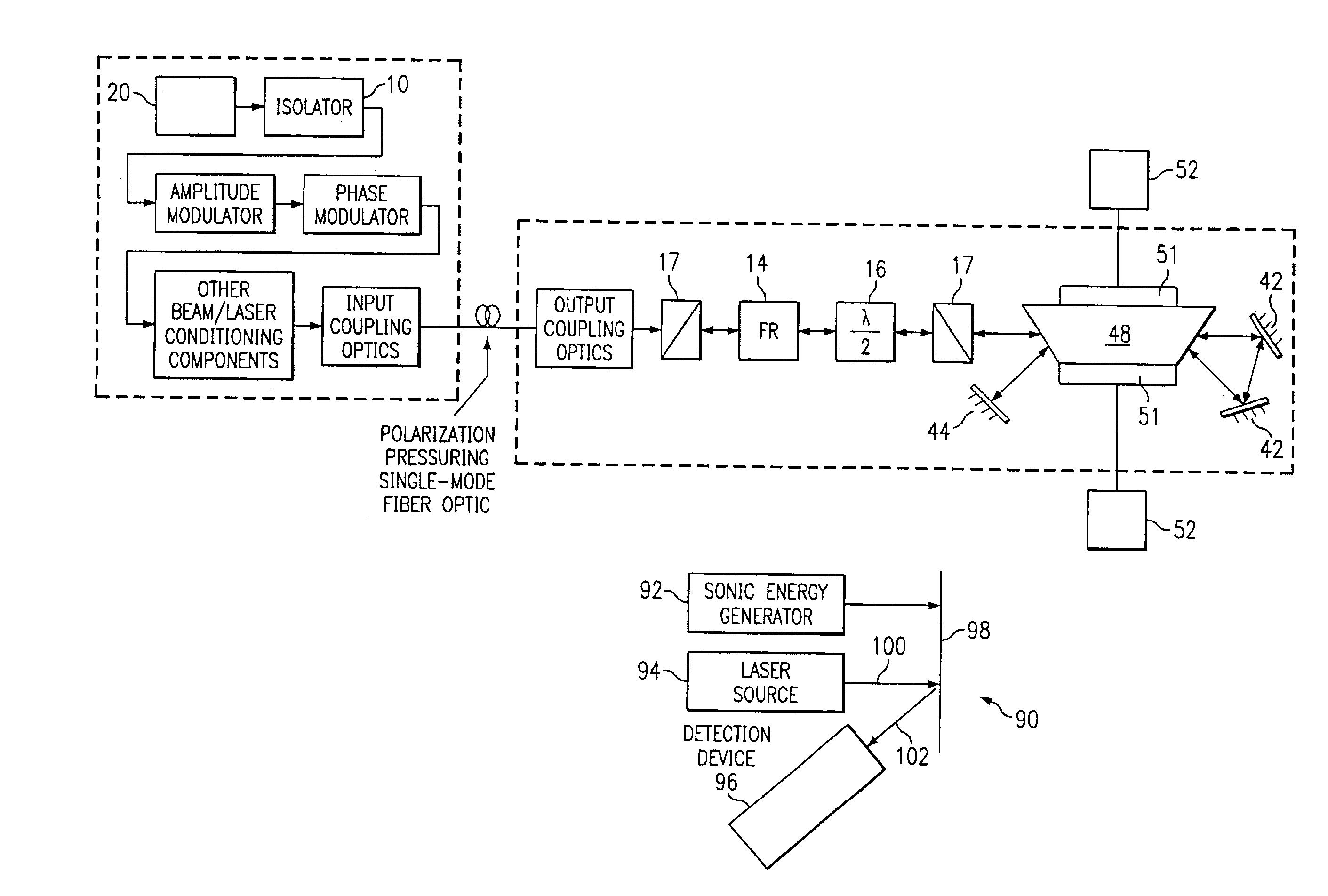
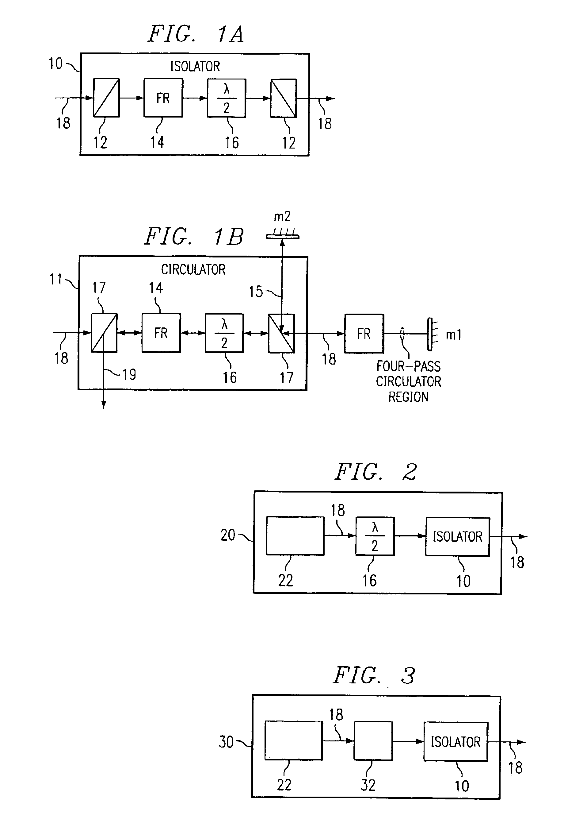
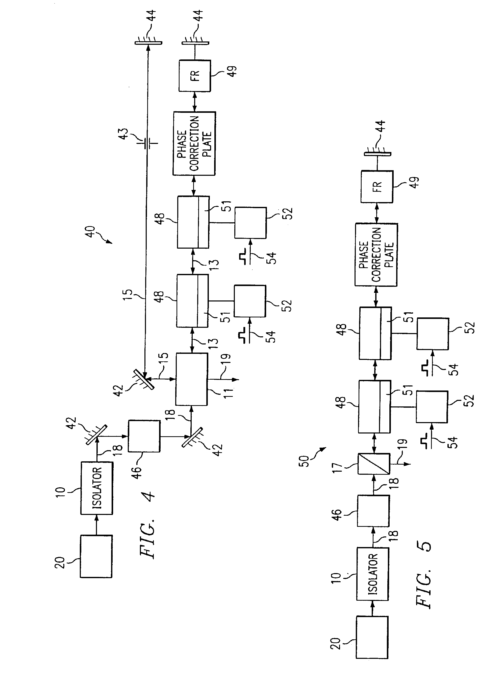
[0040]The present invention provides a system and method for providing amplification of laser light from a solid state laser while maintaining the physical properties of the laser light while minimizing amplification induced distortion. A seed laser possessing desired physical properties including a single longitudinal mode with a desired linewidth is passed through a high-gain laser medium. The center frequency of the seed laser source may be chosen appropriately as to perform within specific applications such as optical interferometry which require very coherent light. The high-gain laser medium may be, for example, optically pumped using a pumping array of laser diodes distributed across the high-gain laser medium. The electric current which drives the pumping array may be a time-varying signal which consequently prov...


PUM


Abstract

A system and method for laser light amplification provides amplification of a laser light beam emitted from a laser light source as low-amplification seed laser light signal. The low-amplification seed laser light signal is transmitted to an amplification component. The amplification component amplifies the low-amplification seed laser light signal by stimulating emissions of the population inversion provided by a pumping diode to generate an amplified laser light signal. The system and method further directs the amplified laser light signal to an output destination. The destination may be an object undergoing laser ultrasound testing. The amplified laser light may reflect with a modulation characteristic of a sound energy wave about the object. The reflected laser light may be collected by an interferometer and used in the detection and characterization of the sound energy wave. The result of the present invention is a system and method of operation providing higher pulse rates, improved pointing stability, and optionally variable pulse rates for a variety of uses, including for non-destructive laser ultrasonic testing of materials.

Description

[0001]This application is a continuation-in-part of U.S. patent application Ser. No. 09 / 344,298, filed Jun. 2, 1999 now U.S. Pat. No. 6,483,859, entitled: “System and Method for High-Speed Laser Detection of Ultrasound”, and is incorporated herein by reference in its entirety.TECHNICAL FIELD OF THE INVENTION[0002]The present invention relates generally to a system and method for laser light amplification and, more particularly, to a system and method for providing amplification of a laser beam emitted from a solid state laser that provides higher pulse rates, improved pointing stability, and optionally variable pulse rates for a variety of uses, including for non-destructive laser ultrasonic testing of materials.BACKGROUND OF THE INVENTION[0003]Amplification of laser light is required for a variety of applications. Long haul telecommunication applications, such as those employing single mode optical fiber, often require optical repeater / amplifiers to boost sagging signal levels. Mat...

Claims


Application Information

Patent Timeline
IPC IPC(8): G01B9/02G02B27/28G01H9/00G01N29/24H01S3/00H01S3/094H01S3/0941H01S3/10H01S3/101H01S3/107H01S3/137H01S3/23
CPCA61B5/0097G01H9/00G01N29/2418H01S3/2341G01N2291/0421H01S3/0941H01S3/2316H01S3/2325H01S3/0064
Inventor DRAKE, JR., THOMAS E.
Owner LOCKHEED MARTIN CORP
Why Eureka
Try Eureka