Rod drop system and method of control rod driving mechanism

A driving mechanism and control rod technology, applied in the control of nuclear reactions, non-rotational vibration suppression, reactors, etc., can solve the problems of covering the active area within a certain period of time, prolonging the time of falling rods, and nuclear hazards, etc., to achieve long-term effective repeated use , avoid damage to the drive mechanism, and eliminate the troublesome effect of maintenance

Active Publication Date: 2014-03-19
SHANGHAI INST OF APPLIED PHYSICS - CHINESE ACAD OF SCI
View PDF11 Cites 13 Cited by
  • Summary
  • Abstract
  • Description
  • Claims
  • Application Information

AI Technical Summary

Problems solved by technology

The buffer only converts the impact energy without reducing the speed, while the damping reduces the speed. When the energy is not fully absorbed, the control rod must rebound. The first damping time is long, and the stroke of the buffer damping is large and the channel is long; after the falling rod covers the active area Performing buffer damping at the same time will prolong the drop time. This is because the buffer damping and damping time will add up at the same time, and the buffer damping stroke will be increased, so the length of the buffer damping channel needs to be increased, because if the channel length is reduced, then Buffer damping must be performed in advance, which will inevitably prolong the time of covering the active area, and the control rod must cover the active area within the specified time. The number of subs may increase geometrically per second, resulting in a nuclear hazard. Therefore, the active area must be covered within a specified time
In addition, the length of the poisonous object of the control rod can only be increased to achieve the purpose of completely covering the active area before and after buffering and damping
Therefore, although the falling speed of the rods is too fast when the reactor is high, this method can be used, but it will increase the length of the buffer damping channel and the length of the control rod poison

Method used


Image

  • Rod drop system and method of control rod driving mechanism
  • Rod drop system and method of control rod driving mechanism
  • Rod drop system and method of control rod driving mechanism

Examples


Embodiment Construction

[0035] Below in conjunction with the drawings, preferred embodiments of the present invention are given and described in detail.

[0036] Such as image 3 As shown, the present invention is a rod drop system 100 of a control rod drive mechanism, which includes: a spring 1, two friction plates 2, a screw transmission mechanism 3 and a sleeve 5, wherein the screw transmission mechanism 3 includes a rotating friction disc 4 and screw assembly 6.

[0037] The inner wall of the sleeve 5 is provided with a dividing plate 51, thereby dividing the inner cavity of the sleeve 5 into upper and lower sections along its length extension direction; the upper surface of the dividing plate 51 is provided with a plurality of first threaded holes 52, two One of the friction plates 2 is fixed on the upper surface of the partition plate 51 by screwing into the first threaded hole 52, that is, fixed at the bottom position of the upper section of the sleeve 5; the outer wall of the lower section of...


PUM


Abstract

The invention relates to a rod drop system and a method of a control rod driving mechanism. The rod drop system comprises a sleeve, a spring, a spiral transmission mechanism and two friction plates, wherein a separation plate which is used for separating an inner cavity into an upper section and a lower section along the length extension direction is arranged on the inner wall of the sleeve; a limiting sleeve which is positioned above the separation plate is arranged in the inner cavity of the sleeve; the spiral transmission mechanism comprises a rotary friction plate which is connected to the outer edge of a guide rod through threads and can move vertically along with the guide rod; one of the two friction plates is fixedly connected to the upper surface of the separation plate, and the other friction plate is fixedly connected to the lower surface of the rotary friction plate and is opposite to the friction plate which is fixedly connected to the upper surface of the separation plate. According to the system and the method, during the drop of a control rod, the effects of effective buffering and complete damping are achieved in sequence, the damage to the control rod driving mechanism is avoided, and the risks of breakage of a chain, bending or damage of a chain wheel shaft and the like are reduced.

Description

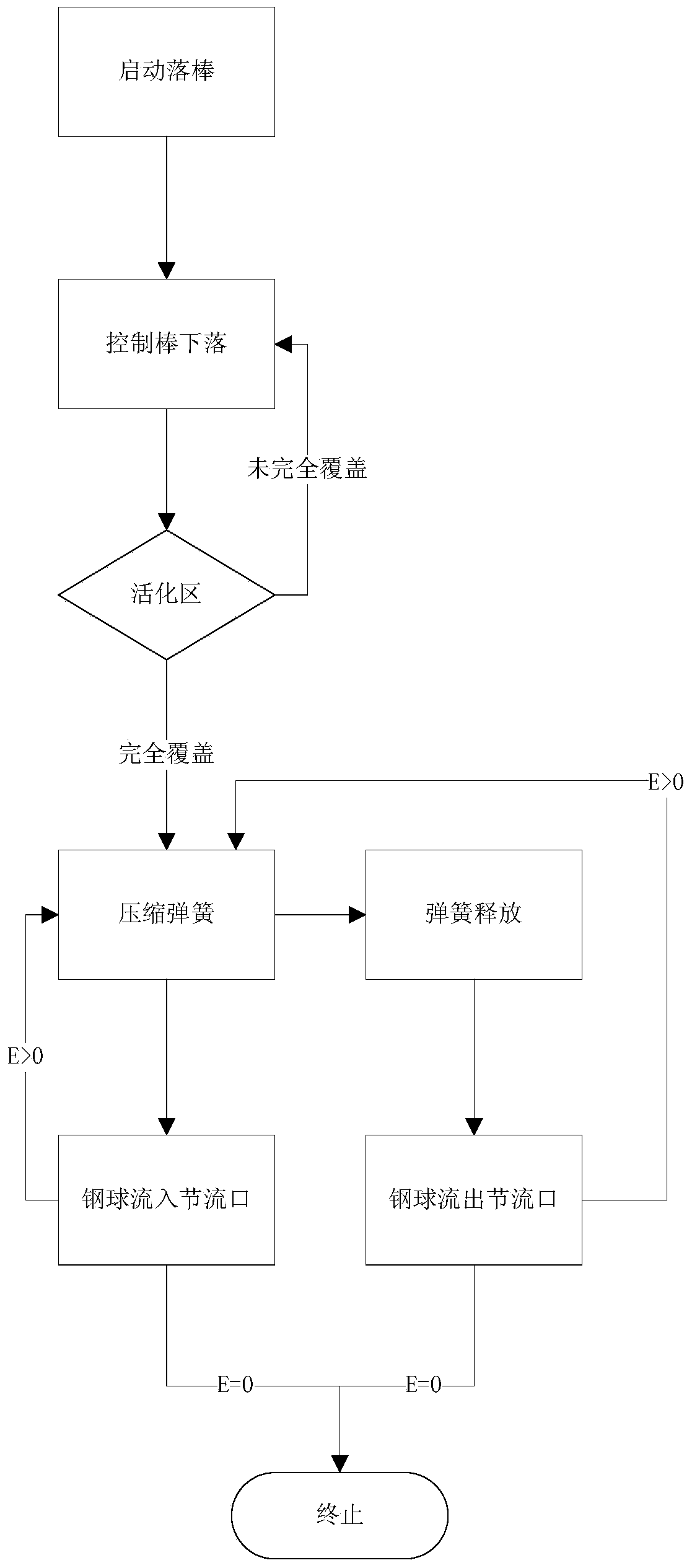
technical field [0001] The invention relates to a nuclear reactor control rod driving mechanism system engineering equipment, in particular to a rod dropping system and method of the control rod driving mechanism. Background technique [0002] As shown in Figure 1(a)-(c), the buffer damper of the control rod drive mechanism of the molten salt reactor in Oak Ridge includes: chain 1', chain pin 2', buffer damping rod 3', buffer spring 4 ', steel ball return spring 5' and steel ball 6'; the principle is to convert the impact energy through the buffer spring 4', and add a throttle (not shown) in front of the flowing steel ball 6' for damping , specifically, its working process includes: start the drop rod; drop the control rod 7' until it completely covers the activation area; compress the buffer spring 4', and the steel ball 6' enters the throttle port; the steel ball return spring 5' is released, the steel ball The ball 6' flows out of the orifice; the above two steps are car...

Claims


Application Information

Patent Timeline
Patent Type & Authority Applications(China)
IPC IPC(8): G21C7/20F16F15/04
CPCY02E30/39Y02E30/30
Inventor 赵汉财刘桂民周兴泰余笑寒黎忠陈堃王晓张东生周雪梅梅龙伟孟令杰
Owner SHANGHAI INST OF APPLIED PHYSICS - CHINESE ACAD OF SCI
Why Eureka
Try Eureka