High thermal conductivity electrode substrate

A thermal conductivity and substrate technology, applied in battery electrodes, circuits, fuel cells, etc., can solve problems such as difficult thermal conductivity

Inactive Publication Date: 2015-05-20
AUDI AG
View PDF6 Cites 0 Cited by
  • Summary
  • Abstract
  • Description
  • Claims
  • Application Information

AI Technical Summary

Problems solved by technology

Achieving the required through-plane thermal conductivity can be especially difficult

Method used


Image

  • High thermal conductivity electrode substrate
  • High thermal conductivity electrode substrate
  • High thermal conductivity electrode substrate

Examples


Embodiment Construction

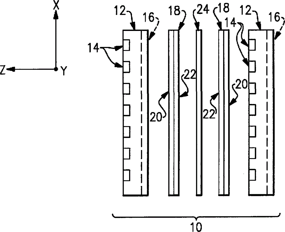
[0012] exist figure 1 An exemplary fuel cell 10 is schematically shown in . A plurality of batteries 10 are arranged adjacent to each other in the Z direction to form a stack (in figure 1 The Y direction is not shown). The fuel cell 10 includes a gas separator 12 having a fuel passage 14 arranged on one side and an oxidant passage 16 arranged on the opposite side. For one type of exemplary gas separator 12, fuel passage 14 and oxidant passage 16 are arranged orthogonally with respect to each other to convey hydrogen-rich fuel and air, respectively. Electrodes 18 are disposed on either side of electrolyte layer 24 and adjacent to gas separator 12 . The components of fuel cell 10 operate in a known manner. In an exemplary embodiment, electrode 18 includes a substrate 20 and a catalyst 22 .

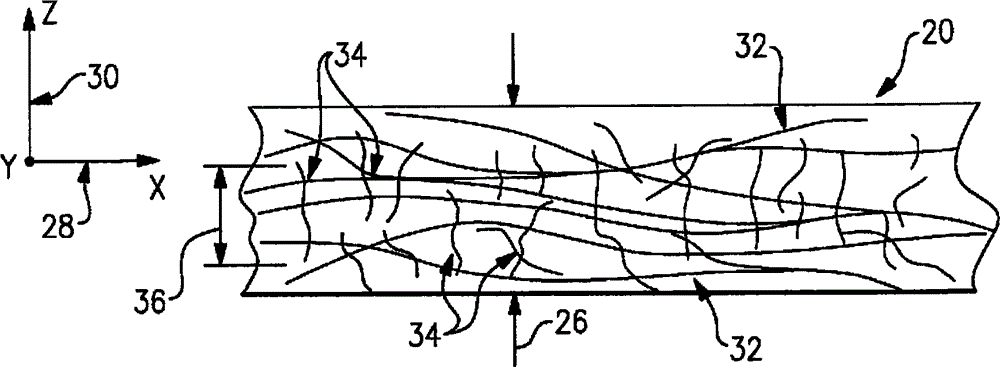
[0013] Typically, substrate 20 is composed of carbon fibers. The type and size of the carbon fibers are selected to provide various desired parameters of the substrate 20 . The exempl...


PUM

PropertyMeasurementUnit
lengthaaaaaaaaaa
lengthaaaaaaaaaa
lengthaaaaaaaaaa

Abstract

An electrode substrate is disclosed that includes a plane and a through-plane direction. First and second carbon fibers are respectively arranged in the plane and through-plane direction. The substrate includes a thickness in the through-plane direction and the second fiber has a length less than the thickness. The first carbon fiber has a length greater than the thickness. In one example method of manufacturing the example substrate, PAN-based carbon fibers are blended with meso-phase pitch-based carbon fibers. A resin is applied to a non-woven felt constructed from the carbon fibers. The felt and resin are heated to a desired temperature to achieve a desired through-plane thermal conductivity.

Description

technical field [0001] The present disclosure relates to carbon-carbon composite materials suitable for use as substrates in fuel cells, for example. Background technique [0002] Some types of fuel cells, such as proton exchange membrane and phosphoric acid fuel cells (PEMFC and PAFC), use porous carbon-carbon composite materials as electrode substrates, also known as gas diffusion layers. In US Patent 4,851,304, an exemplary fuel cell substrate and fabrication process is shown. [0003] A typical method of making the substrate includes: (1) forming a nonwoven mat from chopped carbon fibers and a temporary binder through a wet-laid papermaking process; (2) impregnating or pre-impregnating the substrate with a phenolic resin dissolved in a solvent. felt, followed by solvent removal without curing the resin; (3) pressing one or more layers of felt to a controlled thickness and porosity at a temperature sufficient to cure the resin; (4) heat treating the felt in an inert atmo...

Claims


Application Information

Patent Timeline
Patent Type & Authority Patents(China)
IPC IPC(8): H01M4/58H01M4/36
CPCH01M4/8807H01M8/0234H01M8/0243H01M8/086H01M2008/1095Y02E60/50Y10T428/25Y10T428/249964Y02P70/50
Inventor R·D·布罗
Owner AUDI AG
Why Eureka
Try Eureka