
Direct heating type vacuum welding furnace

A vacuum welding furnace and direct heating technology, applied in welding equipment, electric heating devices, metal processing equipment, etc., can solve the problems of slow speed, difficult to guarantee welding quality, poor heating effect, etc., and achieve high efficiency, good heating effect, The effect of high welding quality

Active Publication Date: 2010-08-18
山东联盛电子设备有限公司
View PDF3 Cites 4 Cited by
  • Summary
  • Abstract
  • Description
  • Claims
  • Application Information

AI Technical Summary

Problems solved by technology

In this way, due to indirect heating, the heating effect is poor, the speed is slow, and the welding quality is difficult to guarantee.

Method used


Image

  • Direct heating type vacuum welding furnace
  • Direct heating type vacuum welding furnace
  • Direct heating type vacuum welding furnace

Examples


Embodiment Construction

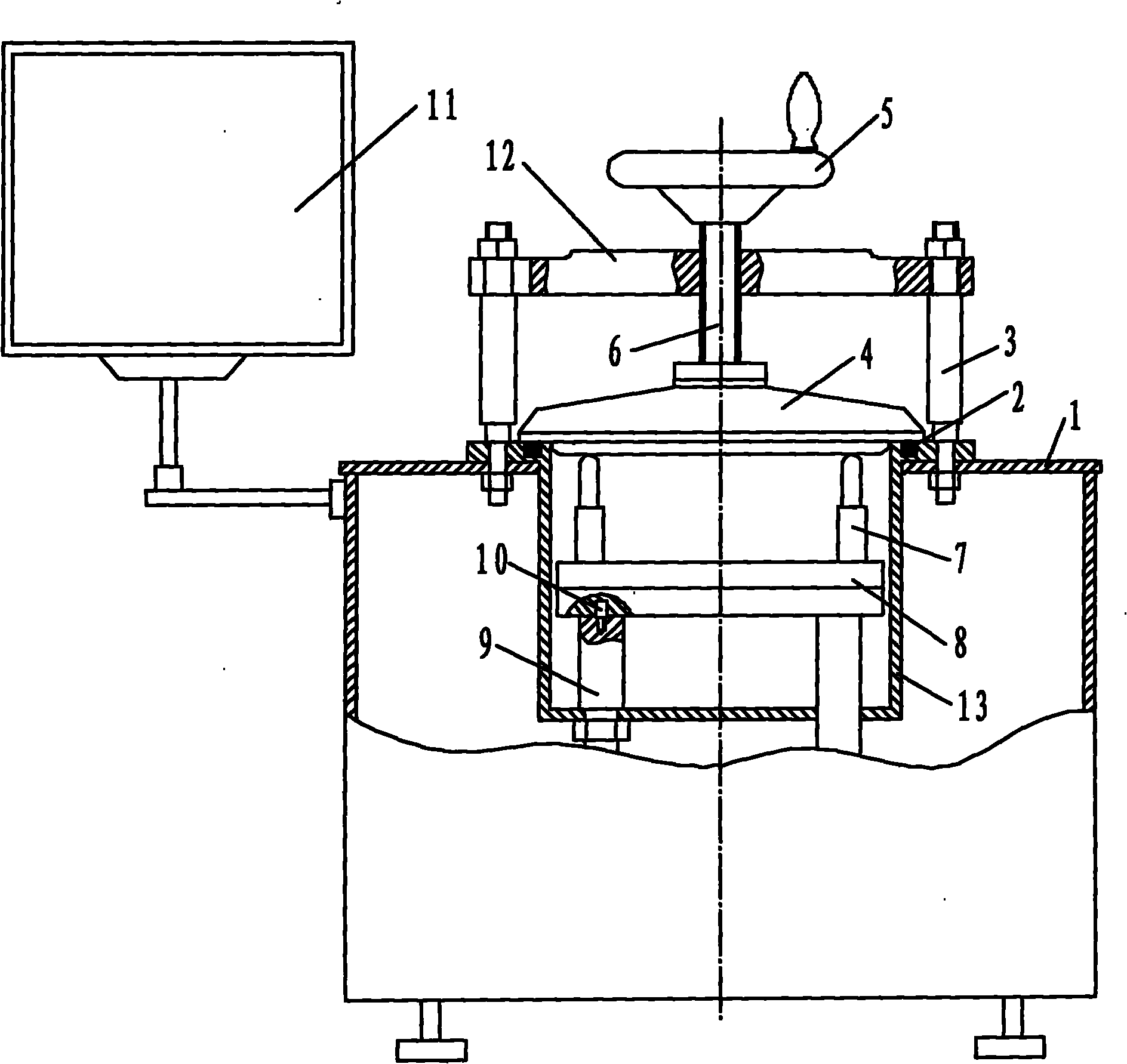
[0015] Such as figure 1 As shown, the vacuum welding furnace of the present invention mainly includes a housing 1, a vacuum chamber 13, an electrode 9, a graphite heating plate 8 and a gland 4, and the vacuum chamber 13 is installed in the housing 1 and fixed together by two columns 3, A connecting body 12 is installed on the column 3 . One end of the connecting body 12 is sleeved on one of the columns, and can rotate around the column. The other end of the connecting body 12 is provided with an opening, which can be stuck on another column, and the connecting body can be made by tightening the nuts on the two columns. 12 are fixed on two uprights. A screw 6 is installed on the connecting body 12 through threaded connection, a handwheel 5 is installed on the upper end of the screw 6, and a gland 4 is installed on the lower end, turning the handwheel 5 makes the screw 6 rotate and move downward, so that the gland 4 is pressed tightly on the The upper end surface of the vacuum...


PUM


Abstract

The invention provides a direct heating type vacuum welding furnace which comprises a shell body, a vacuum chamber, electrodes, graphite heating plates and a gland; the vacuum chamber is sleeved in the shell body and the two are fixed together through two vertical columns; each vertical column is provided with a connecting body, one end of the connecting body is sleeved on one vertical column, and the other end thereof is provided with an opening, and is clamped on the other vertical column through the opening; the connecting body is provided with a screw rod, the upper end of the screw rod is provided with a hand wheel, and the lower end thereof is provided with the gland; a cooling device is arranged in the gland; the two electrodes extend into the vacuum chamber from the lower part of the vacuum chamber and are fixed on the vacuum chamber; the upper end of each vacuum chamber is provided with a positioning column; the graphite heating plates are arranged on the two electrodes through the positioning columns on the upper end of the electrodes; and clamping devices are arranged on the graphite heating plates. The direct heating type vacuum welding furnace directly heats devices on the graphite heating plates through the direct heating type vacuum welding furnace which directly contact with the two electrodes, and has the advantages of good heating effect, high efficiency and high welding quality.

Description

technical field [0001] The invention relates to a vacuum welding furnace used for welding electronic components, belonging to the technical field of vacuum welding furnaces. Background technique [0002] The vacuum welding furnace is a device for heating and welding in a vacuum environment, and its vacuum chamber is evacuated by a vacuum pump. The vacuum chamber is connected with the vacuum pump by pipes, and the two ends of the secondary pole of the transformer are respectively connected with two electrodes, and the two electrodes extend into the vacuum chamber. The heating methods of the existing vacuum welding furnaces are all indirect. The components to be welded for heating are placed in the vacuum chamber, and the quartz heating plate is heated up and down. , The components in the vacuum chamber are indirectly heated and welded together under heating and vacuum. In this way, due to indirect heating, the heating effect is poor, the speed is slow, and the welding quali...

Claims


Application Information

Patent Timeline
IPC IPC(8): B23K3/04
Inventor 马玉水赵仕庆刘桂扬
Owner 山东联盛电子设备有限公司
Features
  • Generate Ideas
  • Intellectual Property
  • Life Sciences
  • Materials
  • Tech Scout
  • Unparalleled Data Quality
  • Higher Quality Content
  • 60% Fewer Hallucinations
Learn More