Method for identifying thermal defects by means of auxiliary heat source under condition of small temperature difference

An auxiliary heat source and thermal defect technology, applied in the field of infrared detection, can solve problems such as influence, achieve the effect of convenient detection and solve the problem of thermal defect detection

Inactive Publication Date: 2010-08-18
HARBIN INST OF TECH +1
View PDF0 Cites 19 Cited by
  • Summary
  • Abstract
  • Description
  • Claims
  • Application Information

AI Technical Summary

Problems solved by technology

[0010] In order to solve the problem that infrared detection can only be used for the detection of building thermal defects in areas where the indoor and outdoor temperature difference is greater than 10°C, and to solve the problem that thermal defect detection is affected by solar radiation and outdoor conditions, the present invention discloses a small temperature difference condition A method for identifying thermal defects with the help of auxiliary heat sources

Method used


Image

  • Method for identifying thermal defects by means of auxiliary heat source under condition of small temperature difference
  • Method for identifying thermal defects by means of auxiliary heat source under condition of small temperature difference
  • Method for identifying thermal defects by means of auxiliary heat source under condition of small temperature difference

Examples


specific Embodiment approach 1

[0027] Specific implementation mode 1: The method for identifying thermal defects with the aid of an auxiliary heat source under the condition of small temperature difference described in this implementation mode, the specific process is as follows:

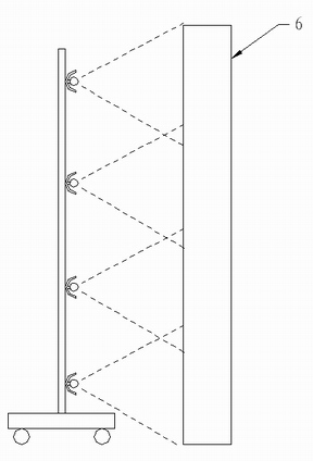
[0028] Adopt auxiliary heat source to irradiate the inner surface of the building wall 6, heat the inner surface of the wall, and stop the irradiation when the temperature of the inner surface of the wall is higher than the outside temperature by x degrees; the value range of x is [3,10]°C;

[0029] Using an infrared thermal imager to detect the temperature field distribution of the inner surface of the wall, and obtain an infrared thermogram representing the temperature field distribution of the inner surface of the wall;

[0030] Analyzing the temperature difference shown in the infrared thermogram, and then obtaining the thermal defects of the building.

[0031] The auxiliary heat source can be realized by using any existing ...

specific Embodiment approach 2

[0040] Specific embodiment 2: The difference between this embodiment and the method of identifying thermal defects with the aid of an auxiliary heat source under the condition of small temperature difference described in specific embodiment 1 is that: the time for controlling the heating of the inner surface of the wall is used as the reason for stopping the heating conditions, the specific process is:

[0041] Using an auxiliary heat source to irradiate the inner surface of the building wall to heat the inner surface of the wall, the irradiation direction of the auxiliary heat source is the normal direction of the inner surface of the irradiated wall, that is, the vertical incidence, and ensure that the irradiation angle is stable, The irradiated surface of the light source is evenly distributed, and the unevenness of the irradiated intensity distribution is within ±5%; and the heat flux density of the auxiliary heat source irradiated to the wall surface is [760W / m 2 ,800W / m ...

specific Embodiment approach 3

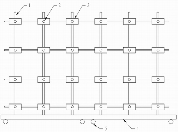
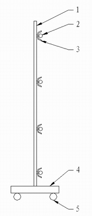
[0068] Specific implementation mode 3: This implementation mode provides a structure of an auxiliary light source, see figure 1 and figure 2 . The auxiliary light source described in this embodiment adopts an assembled structure, which is composed of a movable base 4, a bracket 1, a light source 2, and a reflector 3. The bottom of the movable base 4 is provided with wheels 5, and the bracket 1 is fixed on the movable base. On the upper surface of 4, the support 1 is a planar mesh structure, a plurality of light sources 2 are evenly distributed in a matrix and fixed on one side of the support 1, and a reflector 3 is fixed between each light source 2 and the support 1.

[0069] The auxiliary light source described in this embodiment can adjust the area of ​​the support 1 and the distribution of the light source according to the area of ​​the wall to be detected.

[0070] In practical application, the auxiliary light source described in this embodiment is moved to the front of...


PUM


Abstract

The invention provides a method for identifying thermal defects by means of an auxiliary heat source under the condition of small temperature difference and relates to an identification method of thermal defects. The invention solves the problem that the current infrared detecting method can only be used for detecting the building thermal defects in the regions with the indoor and outdoor temperature difference of more than 10 DEG C and also solves the problem that the existing thermal defect detecting methods can be influenced by solar radiation and outdoor conditions. The method comprises the following steps: firstly, using the auxiliary heat source to irradiate the inner surface of a building wall and heat the inner surface of the wall body, stopping irritation when the temperature of the inside of the wall body rises; secondly, using a thermal infrared imager to detect the temperature field distribution of the inner surface of the wall body, obtaining a thermal infrared spectrum showing the temperature field distribution of the inner surface; and finally analyzing the temperature difference shown in the thermal infrared spectrum to obtain the thermal defects of the building. The method of the invention is applicable to the thermal defect detection of the inner walls and insulated floor of buildings and can also be used for the pipe locating in non-heating seasons of the floor radiant heating system and the pipe locating in non-cooling seasons of the radiant cooling system.

Description

technical field [0001] The invention relates to infrared detection technology. Specifically, it relates to a method for identifying thermal defects. Background technique [0002] my country has comprehensively promoted building energy conservation work for many years, and has gradually advanced from the severe cold and cold regions in the north to regions with hot summer and cold winter and regions with hot summer and warm winter. In order to make the thermal performance of the building envelope meet the requirements of building energy-saving design standards, an insulation layer is often added to the wall. The insulation layer set on the outdoor side of the wall is called external insulation, and the insulation layer set on the indoor side of the wall is called internal insulation. The thermal performance of the building envelope directly affects the indoor environment and building energy consumption. Due to the thermal defects of the walls and roofs, they are concealed ...

Claims


Application Information

Patent Timeline
Patent Type & Authority Applications(China)
IPC IPC(8): G01N25/72G01J5/00
Inventor 方修睦张蕊贾永宏陈新虎
Owner HARBIN INST OF TECH
Why Eureka
Try Eureka