Single-piece cable retention housing for hardened outside plant connector

A connector and housing technology, applied in the field of reinforced connectors, can solve problems such as time-consuming

Inactive Publication Date: 2010-08-18
OFS FITEL LLC
View PDF2 Cites 26 Cited by
  • Summary
  • Abstract
  • Description
  • Claims
  • Application Information

AI Technical Summary

Problems solved by technology

Each of the above steps is time consuming and can require extreme care by a skilled technician to avoid damaging the fragile optical fiber during the process

Method used


Image

  • Single-piece cable retention housing for hardened outside plant connector
  • Single-piece cable retention housing for hardened outside plant connector
  • Single-piece cable retention housing for hardened outside plant connector

Examples


Embodiment Construction

[0021] Embodiments of the present invention will be described more fully hereinafter with reference to the accompanying drawings in which embodiments of the invention are shown. However, the invention may be embodied in many different forms and should not be construed as limited to the embodiments set forth herein; rather, these embodiments are provided so that this disclosure will be thorough and complete, and will fully convey the scope of the invention Passed on to those skilled in the art. Like numbers refer to like elements throughout.

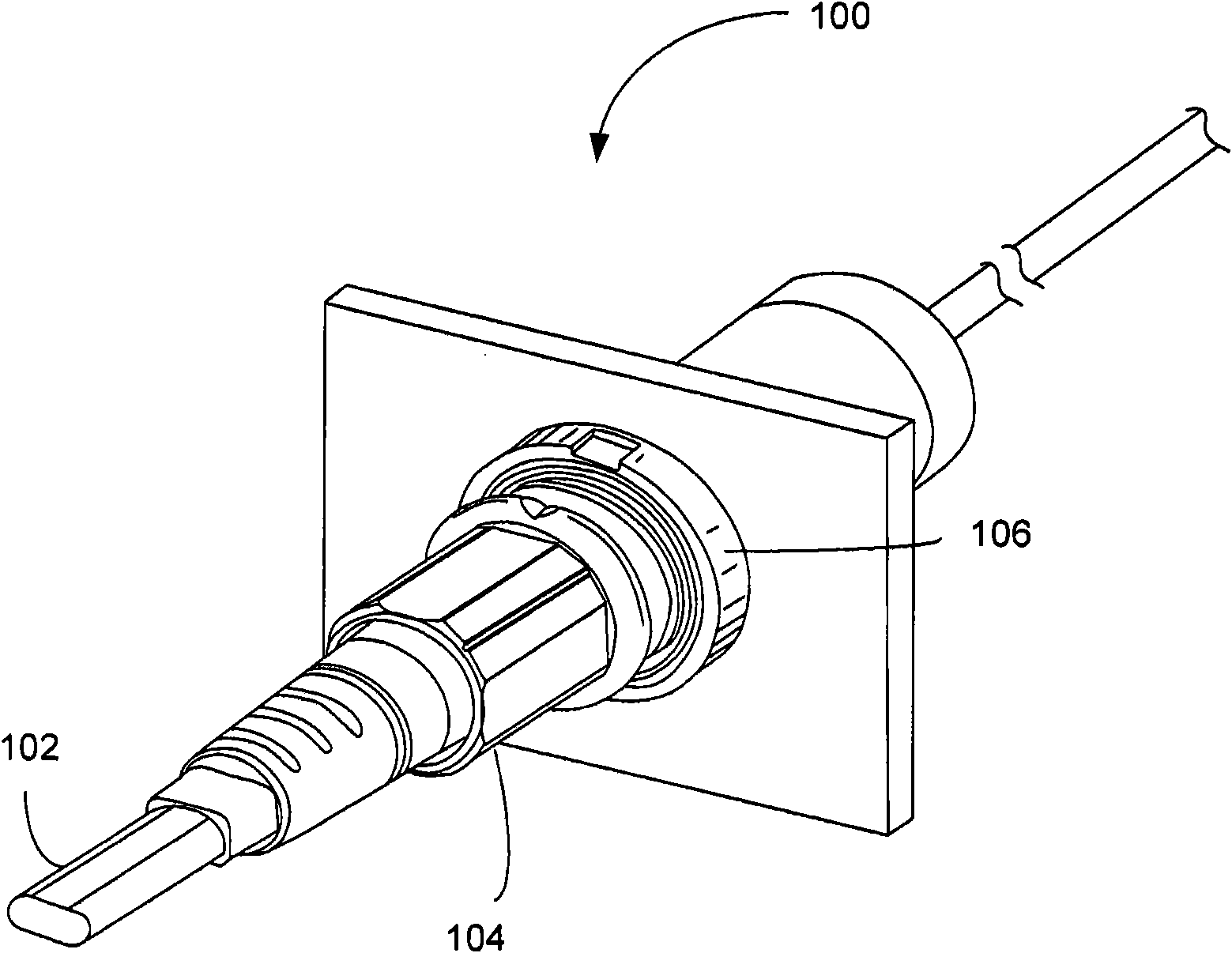
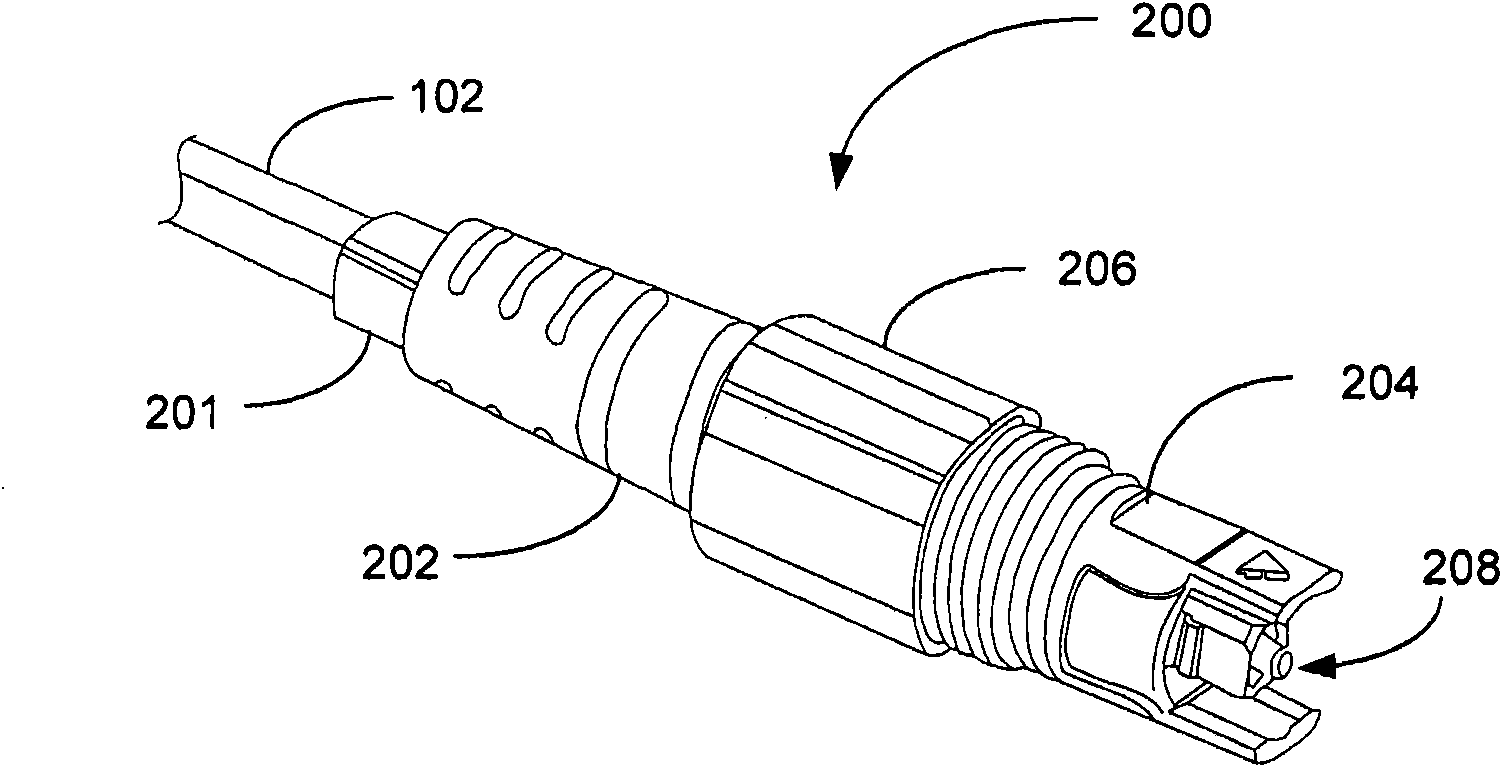
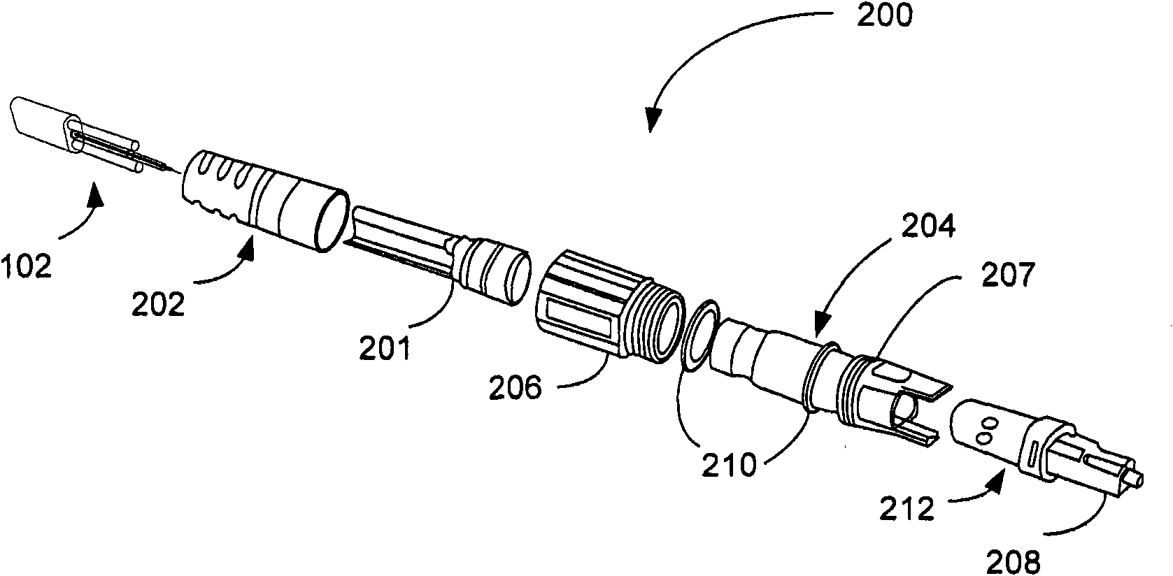
[0022] Embodiments of the present invention enable the use of a one-piece retention housing. An integral retention housing may be used in the termination of a fiber optic cable and it may engage a strength member of the fiber optic cable to provide mechanical retention for the reinforced optical connector assembly and further provide strain relief for the optical fibers within the associated cable assembly .

[0023] The termination of...


PUM


Abstract

According to an example embodiment of the invention, a one-piece retention housing is utilized for terminating an optical fiber cable. The retention housing attaches to strength members within the cable, providing tensile strength and a means for further mating with components of an optical fiber connector assembly. The retention housing is used as part of a kit for terminating and securing the optical fiber cable connector to a complementary receptacle or terminal for drop-cable deployments in optical access networks and outside plant applications.

Description

technical field [0001] The present invention relates generally to fiber optic connectors and, more particularly, to reinforced connectors for drop cable deployment in optical access network and outside line plant applications. Background technique [0002] Optical communication networks are assembled in part by connecting segments of optical fiber between two or more locations. Fusion splicing may provide the best method of joining fiber lengths together, especially if the lengths are to be permanently joined. However, there are many situations, especially in outdoor installations where fiber optic connections need to be easily reconfigurable to connect to different termination points as required and / or to provide strain relief or axial support for the fiber optic cables. In such installation situations, the fusion bonding method may not be a practical option, especially if the connection point is difficult to access (for example, in an inspection hole or located at the ant...

Claims


Application Information

Patent Timeline
Patent Type & Authority Applications(China)
IPC IPC(8): G02B6/38G02B6/44
CPCG02B6/3887G02B6/3888G02B6/3889
Inventor K·B·布拉德利
Owner OFS FITEL LLC
Why Eureka
Try Eureka