Emission current subdivision control circuit based on magnetic source electromagnetic method

A transmission current and segmental control technology, applied in the direction of irreversible DC power input conversion to AC power output, can solve the problem of increasing the electromagnetic interference intensity of the power conversion circuit, increasing the switching loss of the bridge switching device, and affecting the data acquisition of the receiver etc. to achieve the effects of reducing the influence of the primary field, reducing the current off time, and reducing the number of switching times

Inactive Publication Date: 2010-08-18
JILIN UNIV
View PDF4 Cites 32 Cited by
  • Summary
  • Abstract
  • Description
  • Claims
  • Application Information

AI Technical Summary

Problems solved by technology

However, this control technology increases the intensity of electromagnetic interference generated by the power conversion circuit, and increases the switching loss of the bridge switching device; the received signal contains the fundamental frequency and harmonic interference of the PWM control signal, which is helpful for suppressing noise and improving The signal-to-noise ratio and the realization of on-time sampling have adverse effects; moreover, since the existing circuits use bridge switching devices in parallel with reverse diodes as the

Method used


Image

  • Emission current subdivision control circuit based on magnetic source electromagnetic method
  • Emission current subdivision control circuit based on magnetic source electromagnetic method
  • Emission current subdivision control circuit based on magnetic source electromagnetic method

Examples


Embodiment Construction

[0017] Below in conjunction with accompanying drawing when strength is described in further detail:

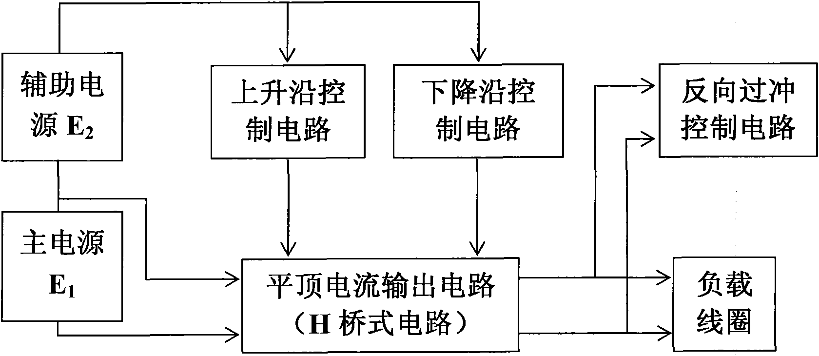
[0018] The circuit adopts four segments to precisely control the output current, and is controlled by the main power supply E 1 The load coil is connected in parallel with the reverse overshoot absorbing circuit through the H-bridge inverter main circuit, and the main power supply E 1 The positive terminal passes through the auxiliary power supply E 2 Finally, the rising edge control circuit and the falling edge control circuit are respectively connected in parallel to the H bridge inverter main circuit to form.

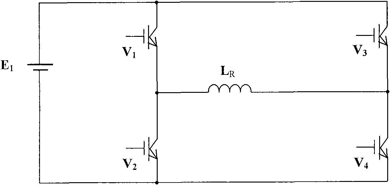
[0019] The H-bridge inverter circuit is composed of switching devices V 1 , V 2 , V 3 , V 4 and coil L R Composition, other parts are connected to the H-bridge inverter circuit.

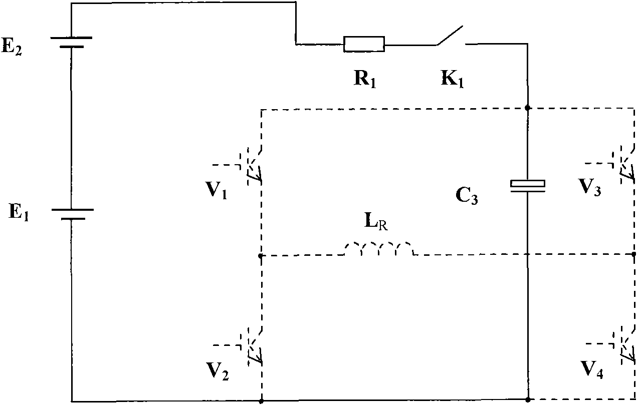
[0020] The rising edge control circuit consists of two parts, the capacitor C 3 Directly connected in parallel to both ends of the power supply and ground of the bridge inverter cir...


PUM


Abstract

The invention relates to an emission current subdivision control circuit based on a magnetic source electromagnetic method. The emission current subdivision control circuit based on a magnetic source electromagnetic method adopts a four-division accurate control mode, and is formed in a way that a primary power supply is connected with loading coils and is connected in parallel with a reverse overshooting control circuit through an H bridge inversion main circuit for outputting flat-top current, and after passing through an auxiliary power supply, the positive end of the primary power supply is respectively connected in parallel with a rising edge control circuit and a falling edge control circuit on the H bridge inversion main circuit. Compared with the prior art, the invention adopts the output current subdivision control, solves the conflict of mutual restriction between the flat-top section control and the rising edge and falling edge control mode, reduces the ripples and the electromagnetic interference of the flat-top current, decreases the turn-off time of the output current, and reduces the effect of the primary field in the shallow detection result interpretation of a large-magnetic moment transient electromagnetic device. Simultaneously, the invention reduces the switching number of the power device, reduces the switching loss of the power device, simplifies the control circuit, saves the cost and improves the efficiency.

Description

technical field [0001] The invention relates to a control circuit for transmitting current waveforms of an electromagnetic detection instrument, in particular to a segmented control circuit for a multi-turn coil transmitting device of a magnetic source. Background technique [0002] Magnetic source electromagnetic method instruments usually use H bridge circuit as the power conversion main circuit of the transmitting device, and the load is inductive. In order to reduce the power loss of the load resistance, a coil load with large inductance and small resistance is usually used, especially in the aviation electromagnetic method and downhole electromagnetic method. The size of the coil is limited in special occasions such as the law, and in fact most of them use small coils with multiple turns. Therefore, special requirements are put forward for the power conversion circuit of the magnetic source electromagnetic method transmitter. [0003] Since the resistance of the load c...

Claims


Application Information

Patent Timeline
IPC IPC(8): H02M7/48
Inventor 于生宝林君周逢道齐林赵阅群
Owner JILIN UNIV
Why Eureka
Try Eureka