Supercharge Your Innovation With Domain-Expert AI Agents!

Burner cap flame stabilization chamber

A flame stabilization, burner cap technology, applied in the direction of burners, gas fuel burners, combustion types, etc., can solve problems such as flameout, flame extinction, and immediate reduction of gas-to-air ratio.

Inactive Publication Date: 2010-08-18
ELECTROLUX HOME PROD CORP NV
View PDF0 Cites 2 Cited by
  • Summary
  • Abstract
  • Description
  • Claims
  • Application Information

AI Technical Summary

Problems solved by technology

[0005] An additional problem is that quickly adjusting the fuel supply to a gas burner from a high burner input rate to a low burner input rate often causes the flame to go out as the fuel is reduced but the momentum of the entraining air stream continues into combustion device, which causes an immediate drop in the gas-to-air ratio, causing flameout

Method used


Image

  • Burner cap flame stabilization chamber
  • Burner cap flame stabilization chamber
  • Burner cap flame stabilization chamber

Examples


Embodiment Construction

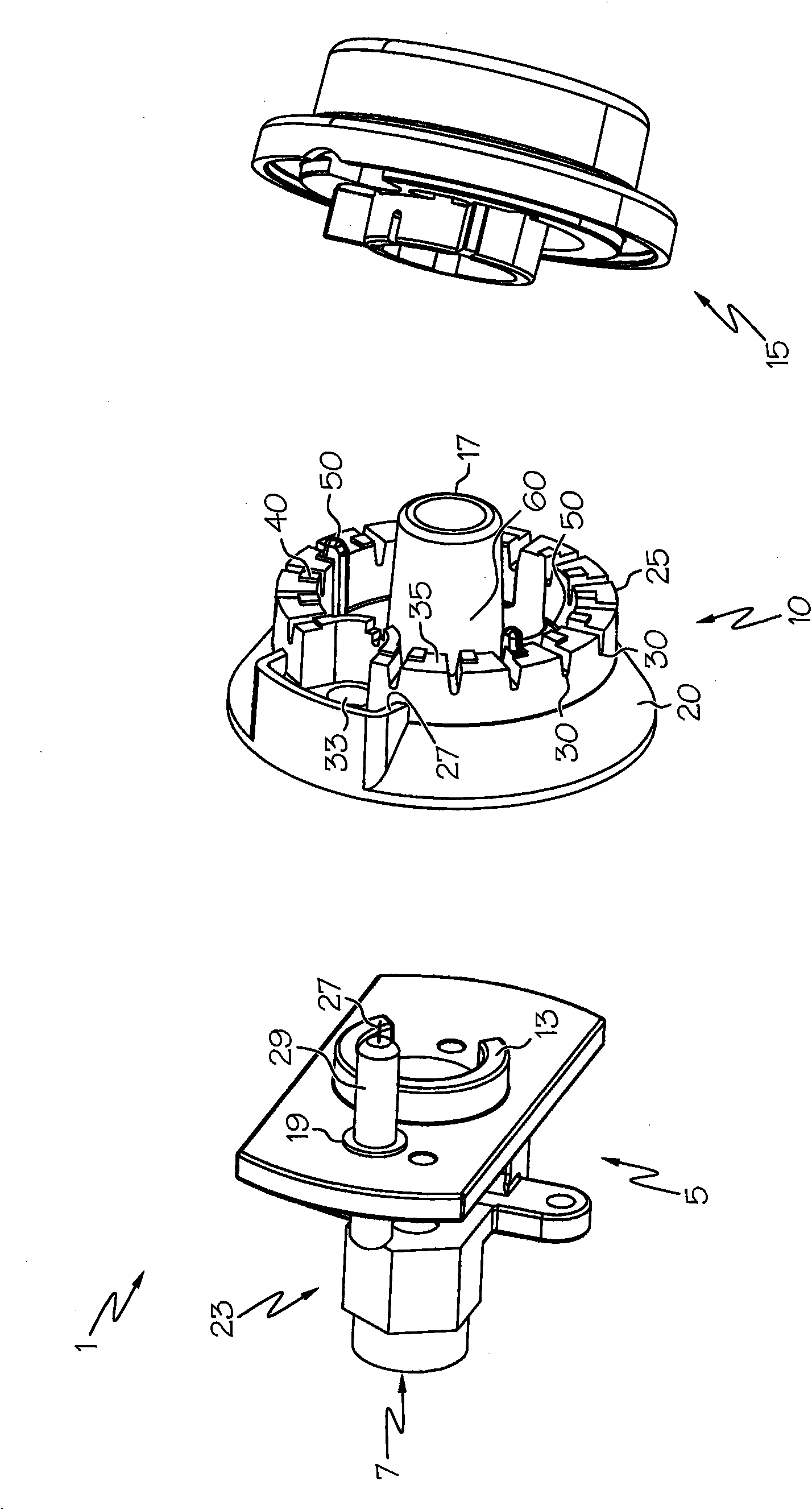
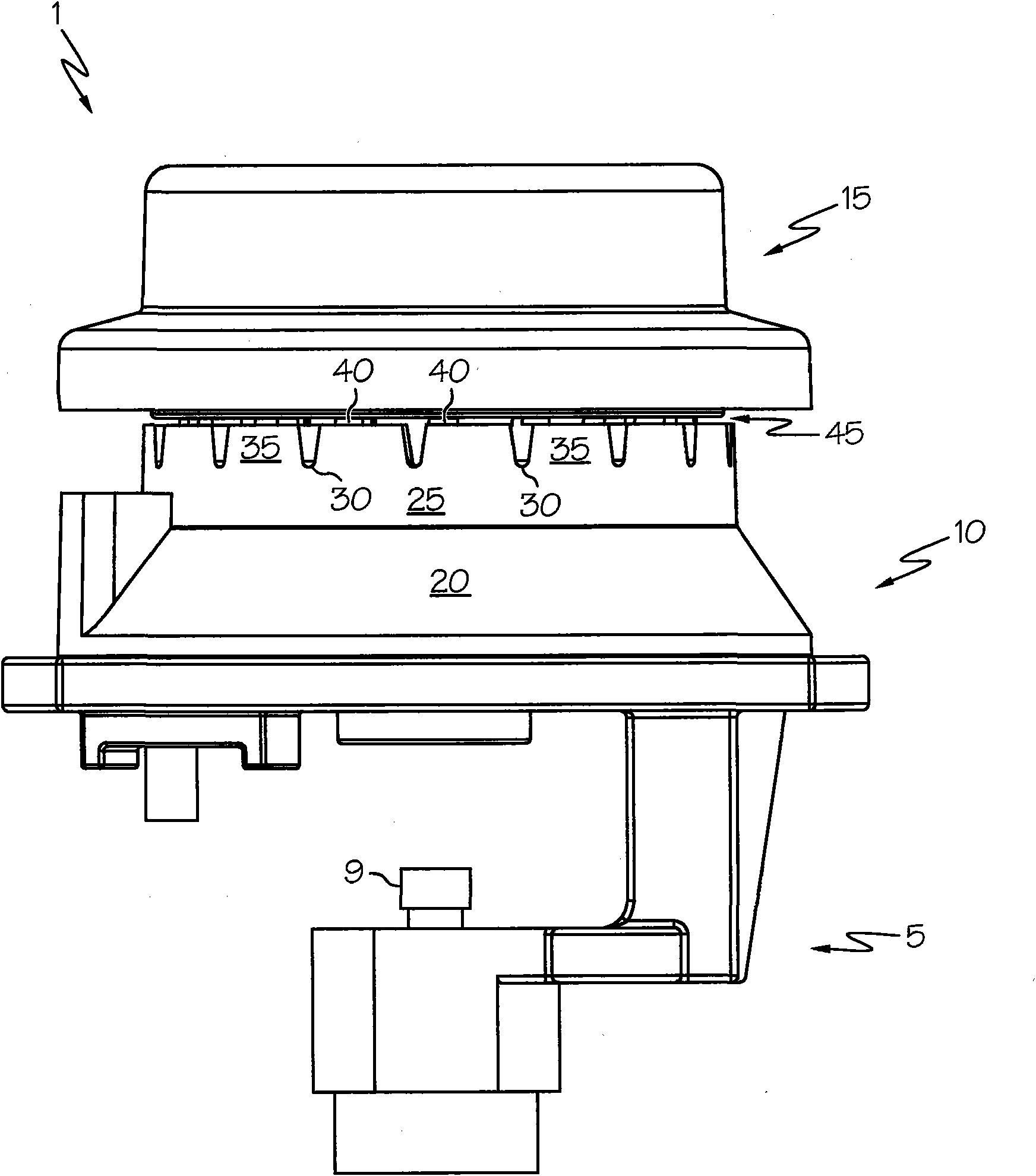
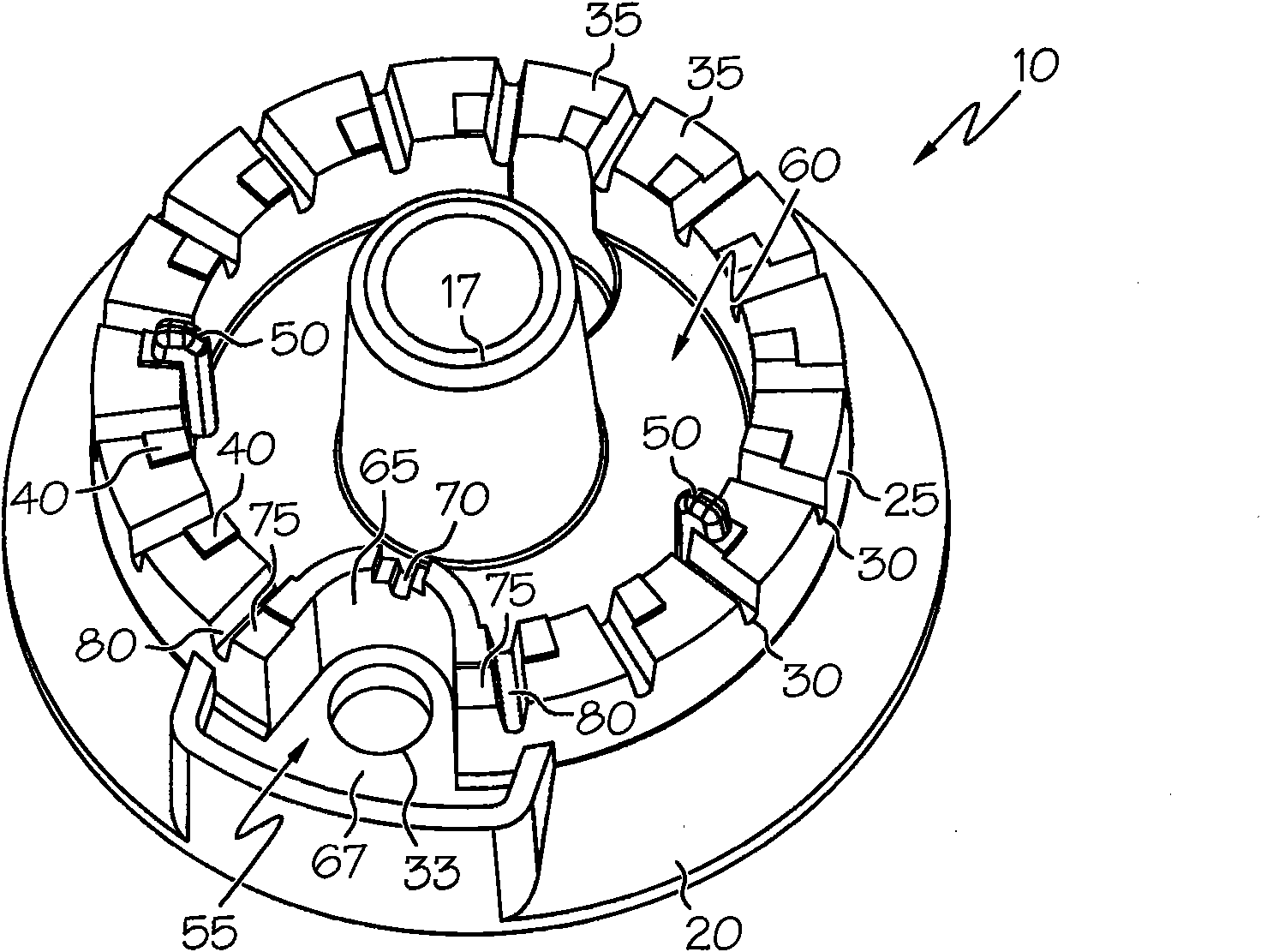
[0021] The invention relates to a cap for a burner having at least one flame stabilization chamber disposed therein. Each flame holding chamber is used to hold a small portion of the gas-air mixture that is combusted in the burner and is located in the burner cap so that the gas-air mixture it holds - The main chamber or plenum of the air mixture is relatively isolated. Thus, the gas-air mixture in the flame stabilization chamber can be used to stabilize the flame when there are pressure changes in the combustion chamber such as may occur when opening or closing the furnace door, which causes disturbances in the burner flame. The invention will now be described with reference to the drawings, wherein like reference numerals are used to refer to like elements throughout. It is to be understood that the various figures are not drawn to scale, either relative to each other or within a given figure, and in particular the dimensions of the various components are arbitrarily drawn ...


PUM


Abstract

A gas burner cap for a cooking appliance includes a top side and a bottom side. The bottom side of the cap is configured to face a corresponding burner body. One or more flame-stabilization chambers are located on the bottom side of the cap.

Description

technical field [0001] The present invention relates to burner caps and, more particularly, to a burner cap for use on a gas cooktop and having a flame stabilization chamber therein. Background technique [0002] Atmospheric gas burners are commonly used as surface units in domestic gas cookers. An important factor in the performance of gas burners is their ability to resist air disturbances in the environment, such as room drafts, fast movement of cabinet doors and, most commonly, rapid operation of oven doors. Oven door operation is particularly annoying because the rapid opening and closing of the oven door often creates a corresponding underpressure and overpressure environment within the oven body. Because the flue, through which the products of combustion exit the furnace, is sized to maintain the desired furnace temperature and is often insufficient to provide sufficient airflow for rebalancing, a large amount of air passes over or around the gas burner. [0003] Ai...

Claims


Application Information

Patent Timeline
Patent Type & Authority Applications(China)
IPC IPC(8): F23D14/06F23D14/26F23D14/58F23D14/76
CPCF23D14/76F23D14/58F23D14/26F23D14/06
Inventor W·M·普赖尔U·哈奈特H·J·道纳斯托格M·帕吉特J·波廷杰
Owner ELECTROLUX HOME PROD CORP NV
Features
  • R&D
  • Intellectual Property
  • Life Sciences
  • Materials
  • Tech Scout
  • Unparalleled Data Quality
  • Higher Quality Content
  • 60% Fewer Hallucinations
Learn More