Liquid crystal display module and assembly method thereof
A technology of a liquid crystal display module and an assembly method, which is applied to instruments, nonlinear optics, optics, etc., can solve the problems of high assembly cost and complicated assembly steps, and achieve the effects of increasing assembly yield, reducing assembly cost, and simplifying assembly steps.
Inactive Publication Date: 2010-08-25
AU OPTRONICS CORP
View PDF5 Cites 14 Cited by
- Summary
- Abstract
- Description
- Claims
- Application Information
AI Technical Summary
Problems solved by technology
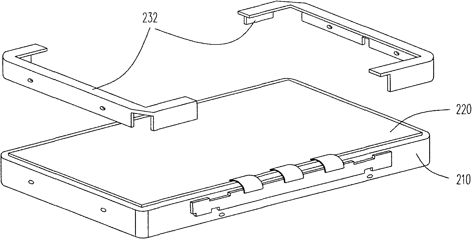
This assembly method also requires a large number of screws to lock the front frames 232 and 234, and requires two assembly processes to assemble the front frames 232 and 234, so the assembly cost is high and the assembly steps are complicated.
Method used
View moreImage
Smart ImageViewing Examples

Examples
Embodiment Construction
Login to View More PUM
 Abstract
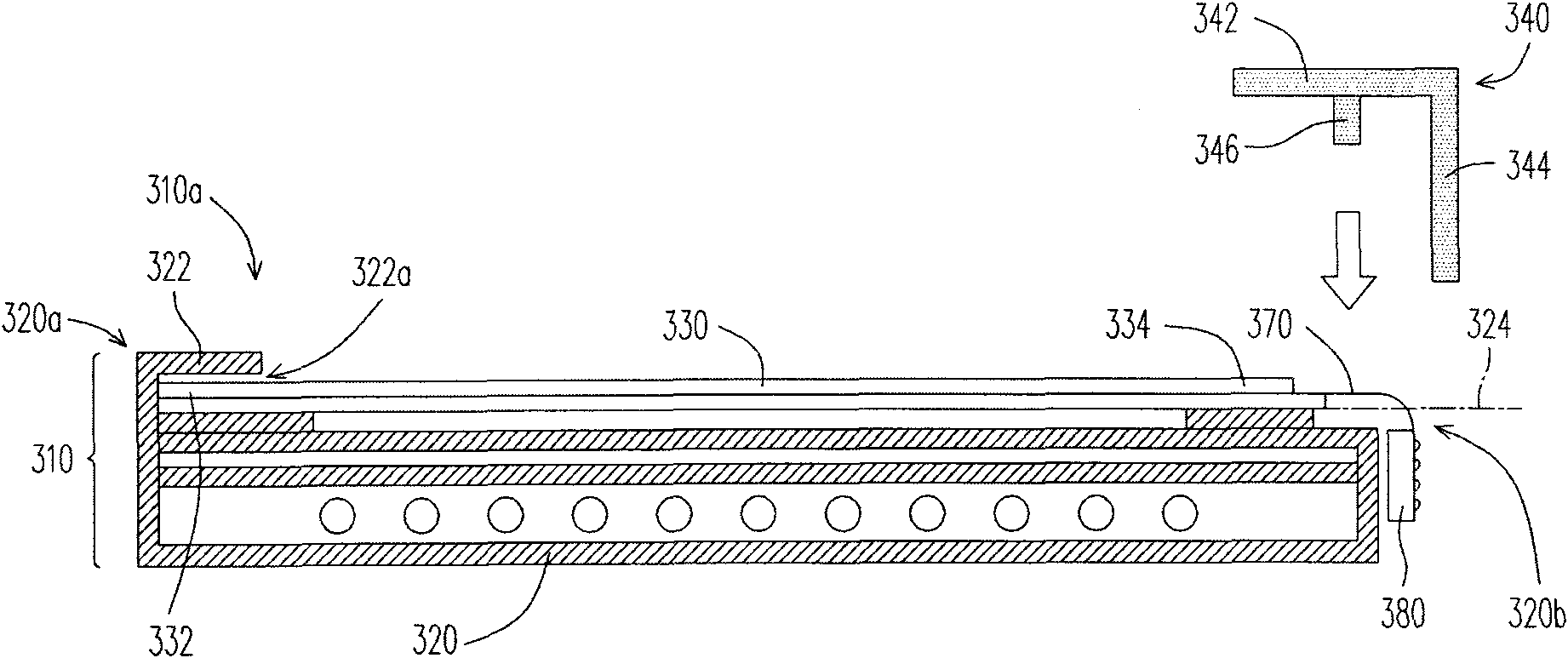
The invention provides a liquid crystal display module and an assembly method thereof, wherein the liquid crystal display module comprises a liquid crystal display panel, a backlight module and a fixing frame. The liquid crystal display panel is configured at one light-emitting side of the backlight module. The backlight module is provided with a bearing frame which is used for bearing the liquid crystal display panel. The bearing frame is provided with a first edge and a second edge which are opposite at the light-emitting side of the backlight module, wherein the first edge is provided with an embedded part protruded at the light-emitting side, whereas the top surface of the second edge is a plane. The crystal liquid display panel is arranged on the plane, and one end of the liquid crystal display panel is inserted in a clamping slot of the embedded part along an extending direction on the plane. The fixing frame is configured on the bearing frame. The other end of the liquid crystal display panel is jointly clamped by the fixing frame and the second edge of the bearing frame; and the fixing frame is provided with a stop part leaning against the side edge of the liquid crystal display panel. The invention can effectively simplify the assembly program and reduces the assembly cost.
Description
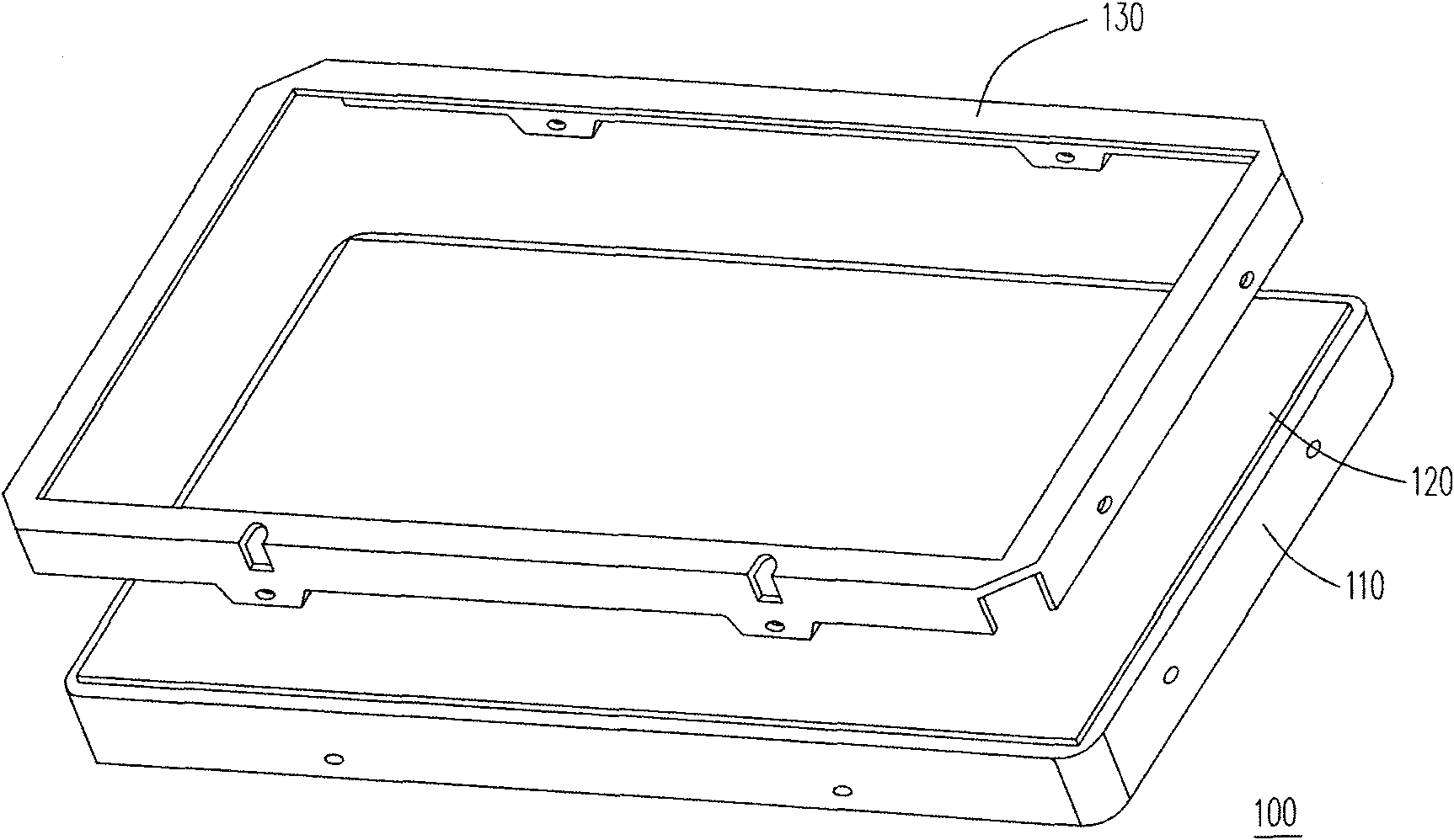
Liquid crystal display module and assembly method thereof technical field The present invention relates to a liquid crystal display module and its assembly method, and in particular to a liquid crystal display module and its assembly method which can simplify the assembly procedure and reduce the assembly cost. Background technique With the increasing maturity of optoelectronic technology and semiconductor manufacturing technology, flat panel display devices are developing vigorously. Among them, the liquid crystal display has gradually replaced the traditional cathode ray tube display due to its advantages of low voltage operation, no radiation scattering, light weight and small size, and has become the mainstream of display products in recent years. Generally speaking, a liquid crystal display module includes components such as a backlight module, a liquid crystal display panel, and a front frame. Location. FIG. 1 is a schematic diagram of the assembly of a known liq...
Claims
Login to View More Application Information
Patent Timeline
 IPC IPC(8): G02F1/1333G02F1/13357
Inventor 梁仲豪赖清坤
Owner AU OPTRONICS CORP
Features
- Generate Ideas
- Intellectual Property
- Life Sciences
- Materials
- Tech Scout
- Unparalleled Data Quality
- Higher Quality Content
- 60% Fewer Hallucinations
Learn More Browse by: Latest US Patents, China's latest patents, Technical Efficacy Thesaurus, Application Domain, Technology Topic, Popular Technical Reports.
© 2025 PatSnap. All rights reserved.Legal|Privacy policy|Modern Slavery Act Transparency Statement|Sitemap|About US| Contact US: help@patsnap.com