

A layering device used in cargo boxes
A layering device and cargo box technology, applied in the mechanical field, can solve problems such as inapplicability, and achieve the effect of simple structure and easy use
- Summary
- Abstract
- Description
- Claims
- Application Information
AI Technical Summary
Problems solved by technology
Method used
Image

Examples
Embodiment 1
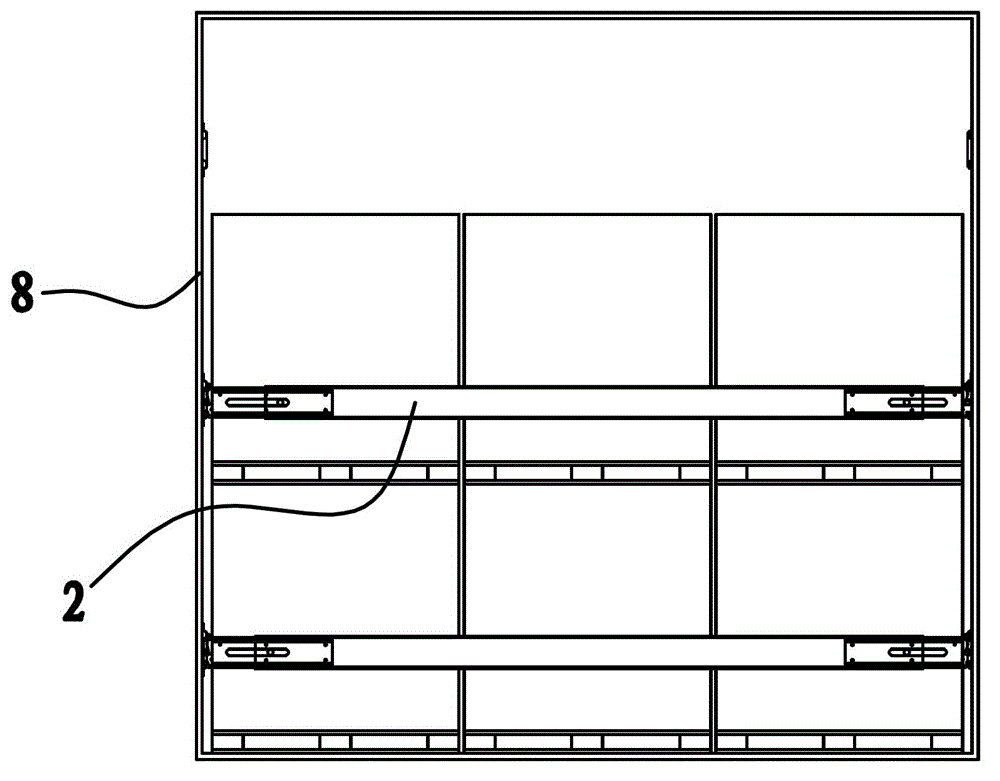
[0047] Such as figure 1 , figure 2 and image 3 As shown, the layering device used in the cargo box includes a positioning track 1, a supporting beam 2 and a fastener. The positioning track 1 is in the shape of a long plate and has a recessed fastening cavity 1a1 along its axial middle. At the same time, there are several positioning holes 1a on the positioning track 1 along its length direction. The positioning track 1 is vertically fixed on the cargo Both inner sides of box 8, see Figure 7 and Figure 8 shown.
[0048]The supporting beam 2 is located between two parallel and facing positioning rails 1, and each supporting beam 2 has a fastening piece at both ends, and there is a clutch structure between the fastening piece and the positioning hole 1a, through which the clutch structure can be fastened The parts are snapped into the positioning hole 1a or disengaged from the positioning hole 1a.
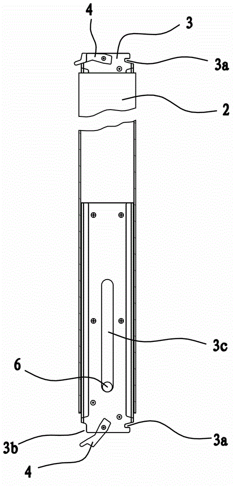
[0049] The fastening part includes a fastening part 3 that can be inser...
Embodiment 2
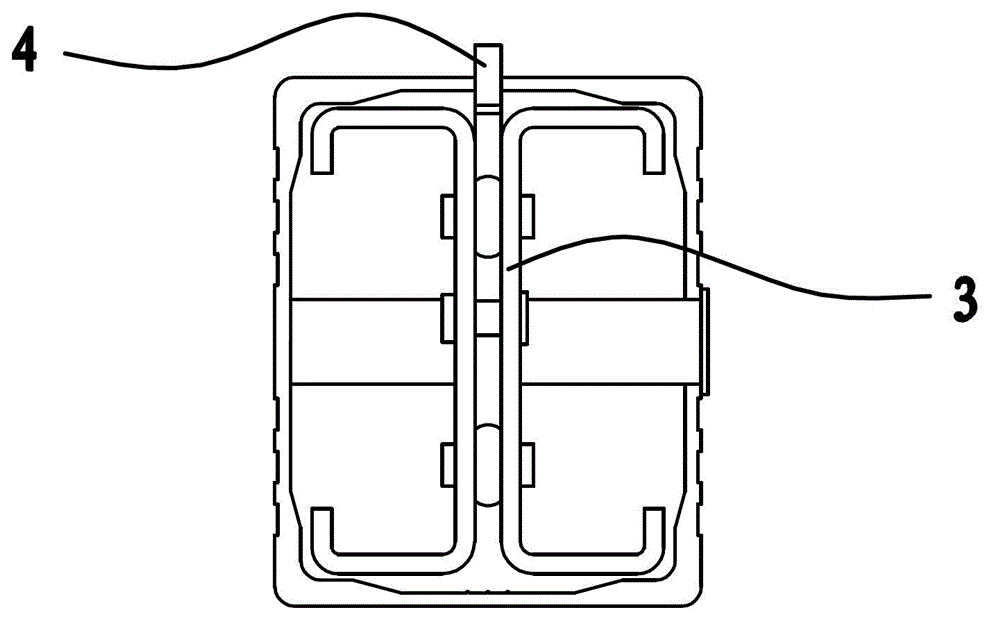
[0058] The structure and principle of this embodiment are basically the same as those of Embodiment 1, except that the fastening structure includes positioning bayonets 3a and relief parts 3b respectively recessed into both sides of the fastening part 3, when the fastening part 3 is inserted into the positioning The positioning bayonet 3a behind the hole 1a is clamped at the edge of the lower side of the positioning hole 1a, and there is a gap between the above-mentioned relief part 3b and the upper edge of the positioning hole 1a for the buckle 3 to disengage from the positioning hole 1a. A retaining bar 4 that can move along it is also connected to the assembly 3, and the retaining bar 4 can move to the relief portion 3b or be separated from the relief portion 3b. In this embodiment, the fastener 3 has a concave guide groove 3d, and part of the retaining strip 4 is located in the guide groove 3d, see Figure 10 shown.
PUM
 Abstract
Description
Claims
Application Information