
flash device

A flash device and light source technology, applied to lighting devices, components of lighting devices, optics, etc., can solve problems such as dirt, heat generation, adverse effects of photography, and expensive

Inactive Publication Date: 2012-02-01
MABUCHI S&T (H K) LTD
View PDF2 Cites 0 Cited by
  • Summary
  • Abstract
  • Description
  • Claims
  • Application Information

AI Technical Summary

Problems solved by technology

In particular, when dirt, etc. are attached to the color temperature conversion filter, the dirt will generate heat due to infrared rays, which may damage the color temperature conversion filter.
It is difficult to realize a color temperature conversion filter that requires such high heat resistance
[0007] Moreover, in the latter strobe device (Patent Document 2), since two xenon discharge tubes are provided, not only becomes expensive, but also the strobe device is enlarged.
In addition, the two lights emitted from the xenon discharge tubes arranged in different positions form two different shadows. Especially when the subject is close, the two flash lights with different color temperatures emitted from the flash device will appear differently. the two shadows of the
In addition, since the optical filter and the liquid crystal whose density can be adjusted are arranged in front of each xenon discharge tube, there is a possibility that the optical filter and the liquid crystal are thermally damaged as in the above-mentioned conventional strobe device.

Method used


Image

  • flash device
  • flash device
  • flash device

Examples


Embodiment Construction

[0064] Embodiments of the present invention will be described below using the drawings.

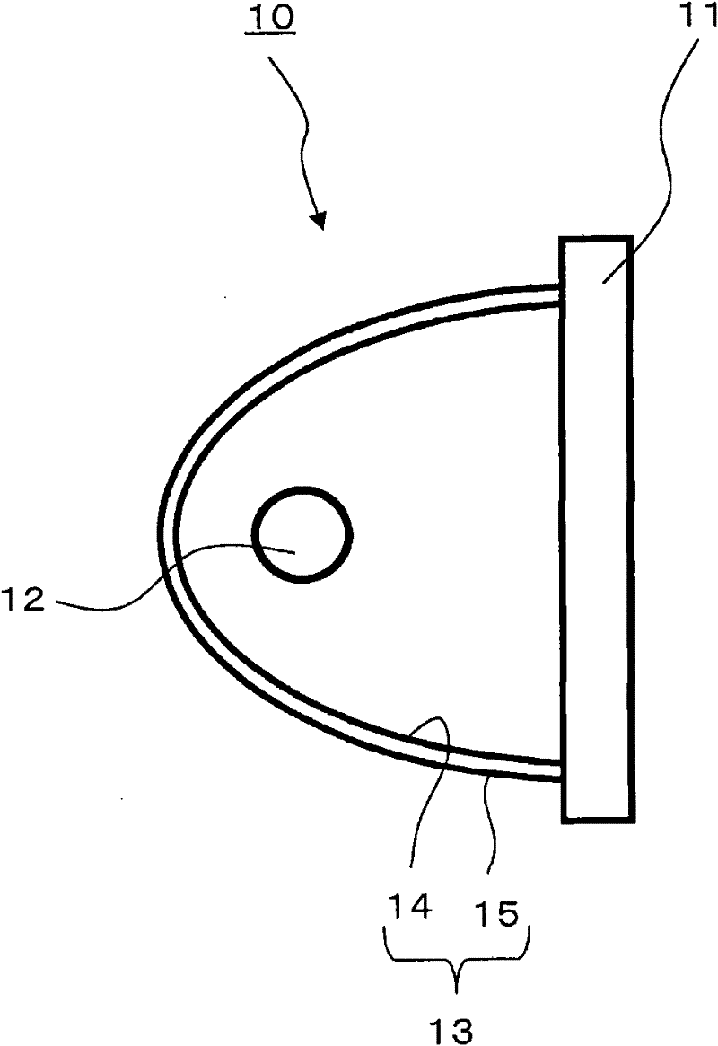
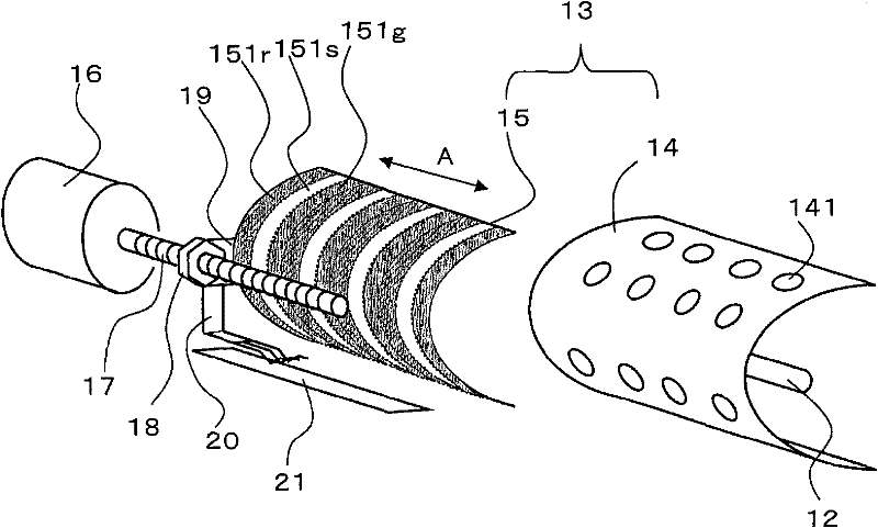
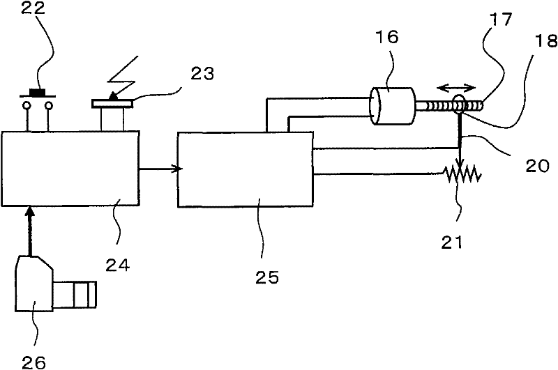
[0065] The strobe device according to the first embodiment of the present invention is such as Figure 1 ~ Figure 3 constructed as shown. figure 1 is a diagram schematically showing the basic structure of the strobe device according to the first embodiment of the present invention, figure 2 is showing figure 1 A diagram showing the structure of the reflector in the flash unit and the structure of the reflector moving mechanism, image 3 It is a figure which shows the structure of the operation control system which operates a mirror moving mechanism.

[0066] exist figure 1 Among them, the strobe device 10 has a linear xenon discharge tube 12 and a reflector 13 as a flash source. The reflection mirror 13 is formed in a plane perpendicular to the xenon discharge tube 12 ( figure 1 In the paper surface) curved (such as elliptic surface) and along the extension direction of the xenon d...


PUM


Abstract

The present invention provides a strobe device capable of effectively imparting light generated from a strobe source to a subject without obstructing photography and capable of adjusting the color temperature of the strobe. The flashlight device has a flashlight source (12) and a reflector (13), and the flash light emitted by the flashlight source (12) and the reflected light of the flashlight reflected by the reflector (13) are emitted toward the front, wherein the flashlight device There is a color distribution variable mechanism (16, 17, 18, 19) which changes the color distribution of the reflection surface of the reflection mirror (13).

Description

technical field [0001] The present invention relates to a flash device having a function of adjusting the color temperature of flash light. Background technique [0002] When taking a photograph, it is desirable that the color tone of the light irradiated on the subject be the same as that of sunlight in the daytime, and the color temperature is used as an index of the color tone. Sunlight has a color temperature of 5,500K, and light from a flash unit is generally about the same as sunlight and has a color temperature of 5,500K. However, when taking photos, there are often large differences between the color temperature of the surrounding environment and the color temperature of the flash light (sunlight). In this case, the color reproducibility of reproduced images and printed photos often deteriorates. . [0003] However, in order to improve the accuracy of color reproduction in such printing, strobe devices having a function of adjusting the color temperature of strobe ...

Claims


Application Information

Patent Timeline
Patent Type & Authority Patents(China)
IPC IPC(8): G03B15/05F21V7/10F21V14/04G02B5/08
Inventor 荻生田进义
Owner MABUCHI S&T (H K) LTD
Learn More