Motor rotor conducting bar punching machine

A technology of motor rotors and guide bars, applied in the field of impact devices, can solve problems such as low production efficiency and unstable quality, and achieve the effects of improving work efficiency, stabilizing product quality, and reducing labor intensity

Active Publication Date: 2010-09-01
CRRC YONGJI ELECTRIC CO LTD
View PDF0 Cites 10 Cited by
  • Summary
  • Abstract
  • Description
  • Claims
  • Application Information

AI Technical Summary

Problems solved by technology

[0003] In order to solve the problems of low production efficiency and unstable quality when manually tapping and tightening the gu

Method used


Image

  • Motor rotor conducting bar punching machine
  • Motor rotor conducting bar punching machine
  • Motor rotor conducting bar punching machine

Examples


Embodiment Construction

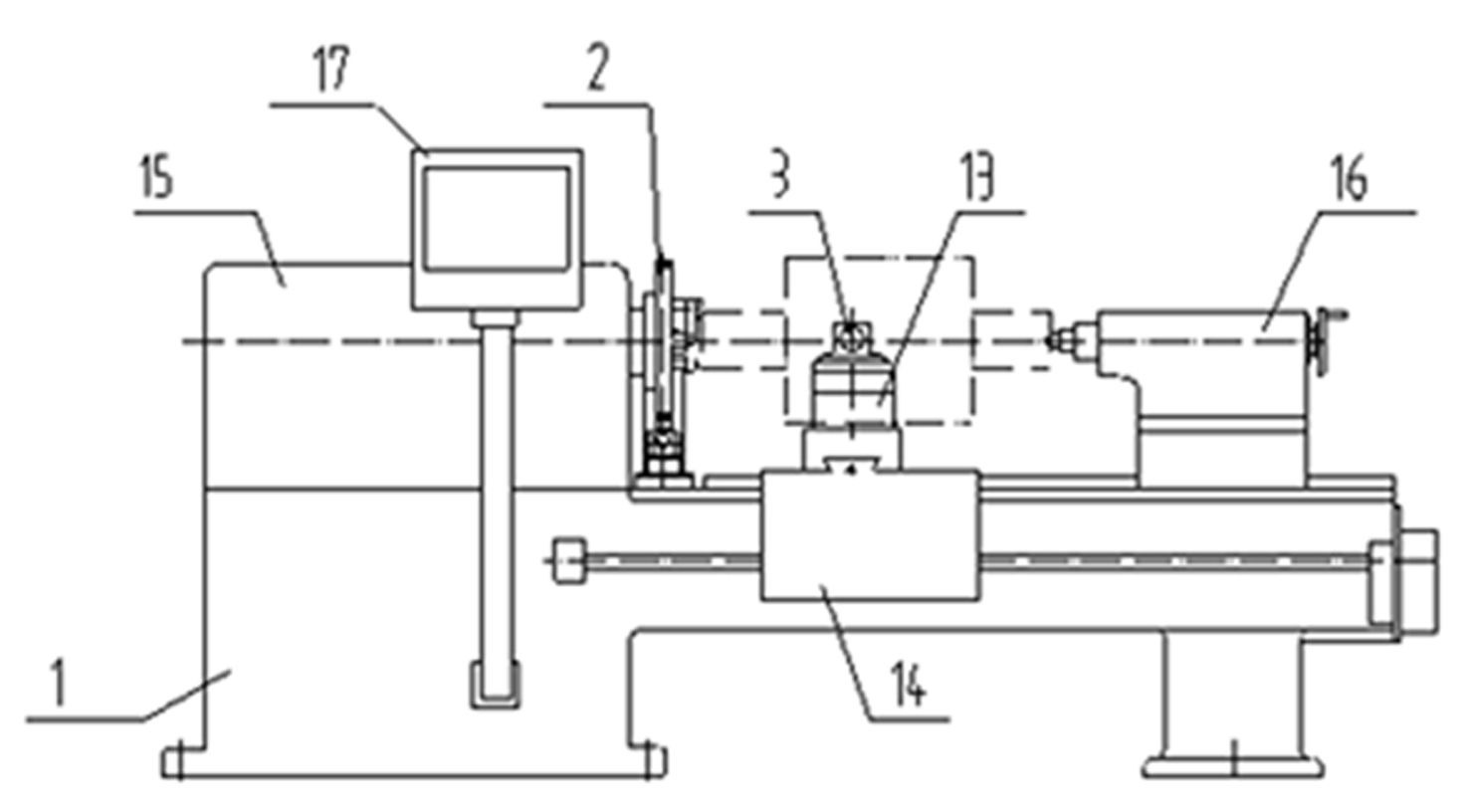
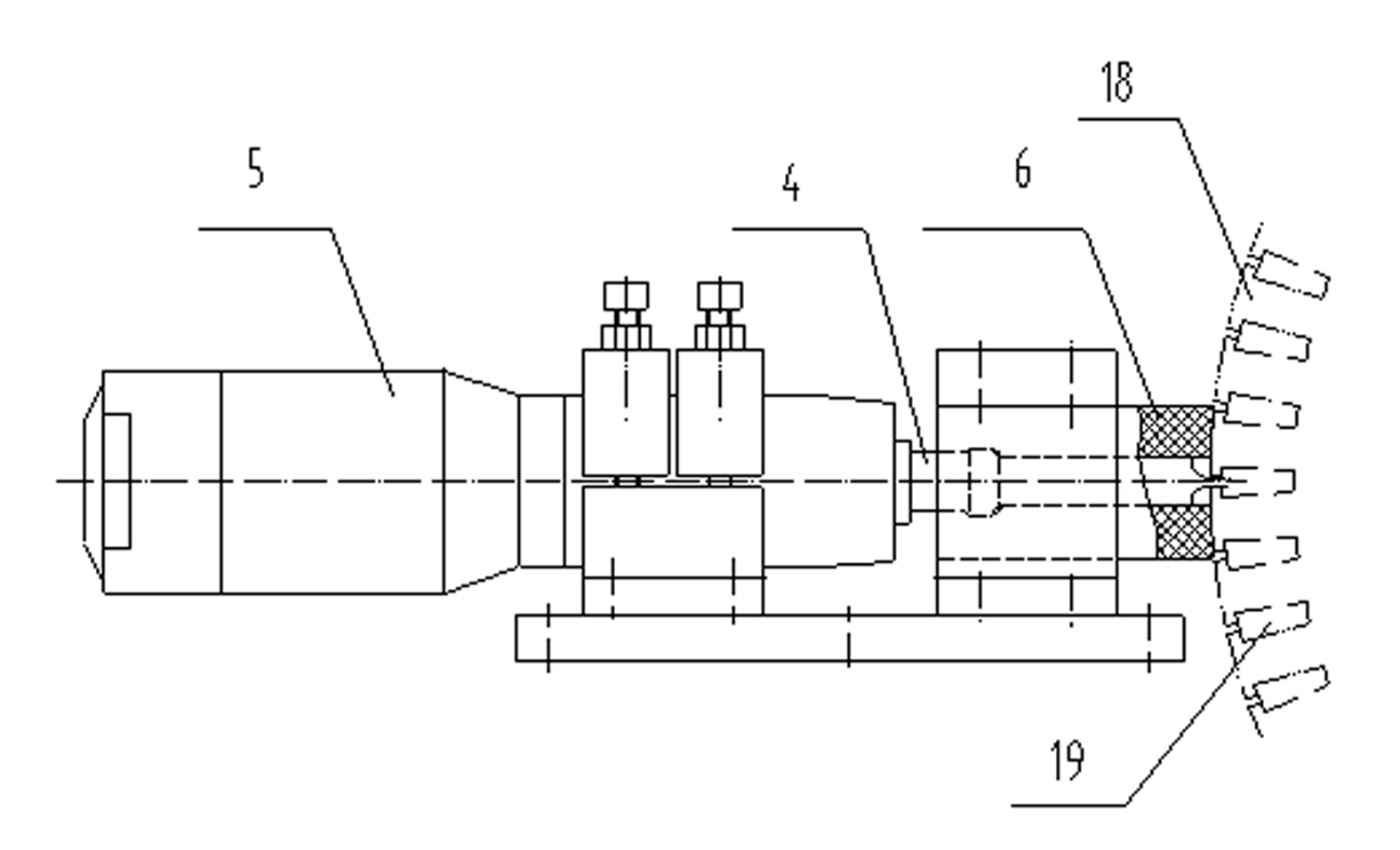
[0011] A motor rotor guide bar flushing machine according to the present invention, such as figure 1 As shown, it includes a clamping mechanism fixed on the machine body 1, a feed mechanism controlled by a control unit, and an intermittent indexing positioning device 2. The feed mechanism is fixed with an impact device 3 controlled by a control unit. The device 3 comprises a percussion cylinder 5 to which a punch 4 is connected, controlled by a control unit. The control unit is contained in the control box 17.

[0012] The impact device 3 also includes a guide block 6 arranged in front of the punch 4 to cooperate with the punch 4 . The guide block 6 has the functions of limiting the angular displacement of the punch, buffering and controlling the depth of the deformation groove. Guide block 6 can be made of elastic material.

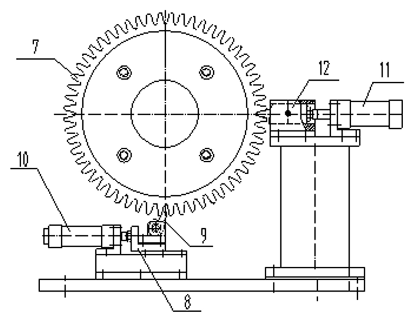
[0013] As shown in Figure 3, the intermittent indexing positioning device 2 includes a ratchet mechanism and a positioning device. The ratchet mechan...


PUM


Abstract

The invention relates to a punching device for solving the problems of low quality efficiency and unstable quality when tension motor rotor conducting bars are manually knocked. The motor rotor conducting bar punching machine comprises a clamping mechanism, a feeding mechanism and an intermittent indexing positioning device, wherein the clamping mechanism is fixed on a machine body, the feeding mechanism and the intermittent indexing positioning device are controlled by the control unit, a punching device controlled by the control unit is fixed on the feeding mechanism and comprises a punching air cylinder which is connected with a formed punch and controlled by the control unit, a control mechanism starts the punching air cylinder to punch the formed punch into a conducting bar to form a deformed groove, and the intermittent indexing positioning device returns to the next conducting bar groove position to carry out operation after one conducting bar is punched. The invention changes a traditional manual operation mode and can lighten the labor intensity, improve the working efficiency, stabilize the product quality and achieve the design requirements, thereby realizing the automatic and diversified product production.

Description

technical field [0001] The patent of the present invention relates to an impact device, specifically a device for impacting and tightening the guide bar of a motor rotor. Background technique [0002] During the assembly process of the AC traction motor rotor guide bar, the principle of deformation and extrusion is used to tighten it in the iron core to avoid displacement during operation. The length direction is extruded into several U-shaped grooves, so that it is deformed and tightened in the groove of the guide bar. In the traditional process, the blunt flat shovel is manually hit with a hand hammer on the upper part of the guide bar to cause deformation. Such an operation makes the depth and length of the deformation groove uneven, and there are differences in the tension of each part. Human factors will make the assembly quality of the guide bar unstable, and it is difficult to meet the quality required by the design. The efficiency is low, the labor intensity is hig...

Claims


Application Information

Patent Timeline
IPC IPC(8): H02K15/09
Inventor 孙永奎耿新民薛红军杨临州张恒庞登高赵天成戈文
Owner CRRC YONGJI ELECTRIC CO LTD
Why Eureka
Try Eureka