
Tyre with shell and carrier structure

A supporting structure and tire technology, applied to tire parts, non-pneumatic tires, transportation and packaging, etc., can solve problems that affect tread turning, temperature rise, etc.

Inactive Publication Date: 2010-09-01
MICHELIN & CO CIE GEN DES ESTAB MICHELIN
View PDF1 Cites 8 Cited by
  • Summary
  • Abstract
  • Description
  • Claims
  • Application Information

AI Technical Summary

Problems solved by technology

[0005] In U.S. Patent US 4 235 270, although the supporting structure of the tire described in it cooperates with the sidewall of the tire to transmit the force between the inner annular ring and the outer annular ring, this bulky structure must Will greatly affect the steering of the tread
[0006] The limitation of this dual function is that many factors must be compromised during the tire's design phase, these factors typically include: weight, complexity of construction, maximum transmissible torque and tire deformation, which can cause internal heating

Method used


Image

  • Tyre with shell and carrier structure
  • Tyre with shell and carrier structure
  • Tyre with shell and carrier structure

Examples


Embodiment Construction

[0032] As indicated before, the invention concerns a tire considered essentially from the point of view of its construction.

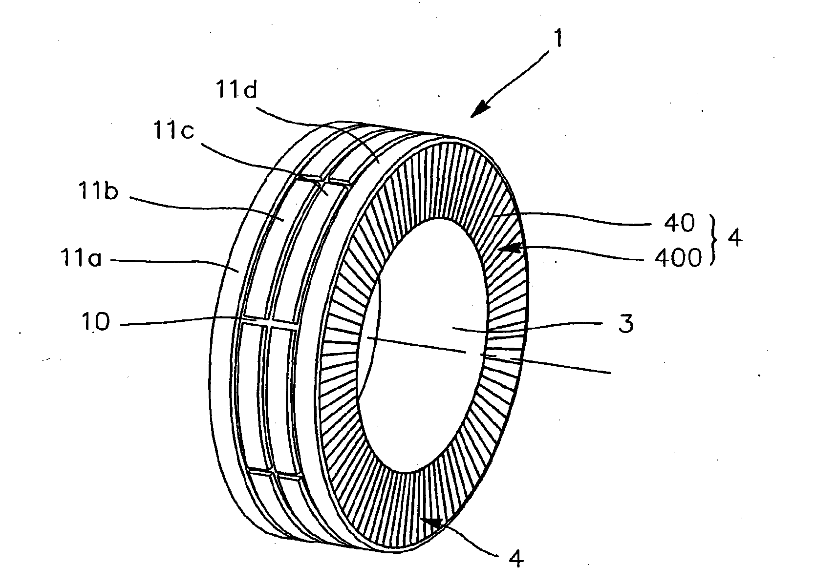
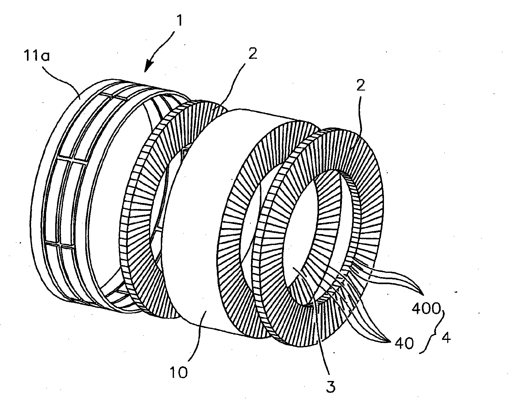
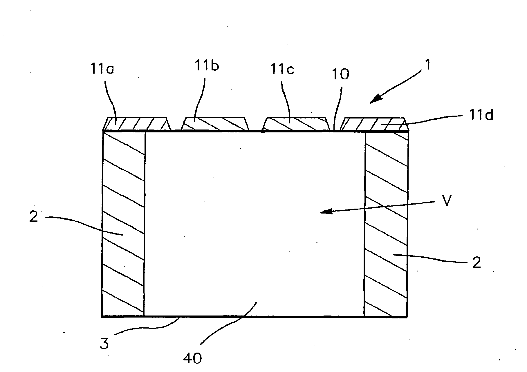
[0033] The tire according to the invention comprises an outer layer at least partly made of rubber, which delimits in a sealed manner an inner annular space V( image 3 ), and has a crown 1 and two sidewalls 2.

[0034] A crown 1 is associated with each of the two sidewalls 2 and defines, on its outer surface, a tread.

[0035] The tire according to the invention also comprises at least one inner annular ring 3 , an outer annular ring 10 and a support structure 4 .

[0036] The inner annular ring 3 is arranged concentrically inside the crown 1 and at a distance from the crown 1 , while the support structure 4 is at least partially housed in the inner space V and connects the inner annular ring 3 to the outer annular ring 10 , which The support structure 4 is the main part of the crown 1 .

[0037] When the tire is in use, the annular space V delimit...


PUM


Abstract

The invention relates to a tyre including a casing at least partially made of gum, defining an inner annular volume and having a top (1) defining a tread and two flanges (2) connected to said top (1), as well as a carrier structure (4). According to the invention, the carrier structure (4) is pressurised and divides the annular volume of the tyre into a plurality of compartments (400) or cells, and the flanges (2) are connected to or integrated in the carrier structure (4).

Description

technical field [0001] In general terms, the invention relates to a device for a motor vehicle. Background technique [0002] More specifically, the invention relates to a tire comprising an envelope at least partly made of rubber, the outer layer delimiting an inner annular space, which in operation is subjected to inflation pressure; has a crown and two sidewalls, said crown is joined to each of said two sidewalls, and said crown defines a tread; said tire also includes at least one inner annular ring, outer annular ring and a support structure, said inner annular ring being arranged concentrically inside said crown at a distance from said crown, said outer annular ring belonging to said crown of said tyre, said supporting structure being at least Partially accommodated inside the interior space, and connects the outer annular ring and the inner annular ring. [0003] Such a tire is described, for example, in US Patent US 4 235 270 . [0004] In a conventional tire, the...

Claims


Application Information

Patent Timeline
Patent Type & Authority Applications(China)
IPC IPC(8): B60C7/00B60C7/12
CPCB60C7/00B60C7/12B60C7/143B60C5/24Y10T152/10522Y10T152/1054
Inventor M·迪尔
Owner MICHELIN & CO CIE GEN DES ESTAB MICHELIN
Learn More