
Exploding device with multi-varying section and detonator applying same

A technology of variable cross-section and detonator, which is applied to weapon accessories, fuzes, offensive equipment, etc., can solve the problem of not meeting the requirements of use, and achieve the effect of being conducive to fully automated production, convenient positioning, and simplified process

Inactive Publication Date: 2012-11-07
UNIV OF SCI & TECH OF CHINA
View PDF1 Cites 3 Cited by
  • Summary
  • Abstract
  • Description
  • Claims
  • Application Information

AI Technical Summary

Problems solved by technology

Moreover, the first generation of flyer detonators cannot meet the requirements of use in harsh environments such as high temperature, high pressure and high-speed impact.

Method used


Image

  • Exploding device with multi-varying section and detonator applying same
  • Exploding device with multi-varying section and detonator applying same
  • Exploding device with multi-varying section and detonator applying same

Examples


Embodiment 1

[0019] Embodiment 1 One-stage variable cross-section flyer type excitation device and the detonator using the device

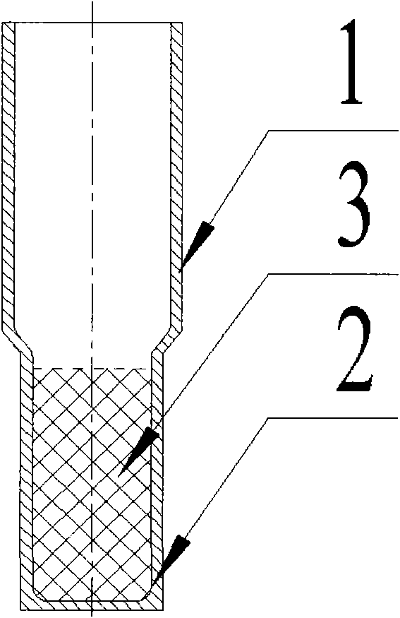
[0020] see figure 1 , The variable cross-section inner cap of the variable cross-section flyer excitation device is divided into upper and lower parts. The outer diameter of the upper cylinder body 1 is larger than the outer diameter of the lower cylinder body 2 . The inner hole of the lower cylinder body 2 is used for installing four medicines 3 . If the outer diameter of the upper cylinder of the excitation device is sleeved in the inner hole of the detonator shell so that the two are closely matched, a prompt detonator with a first-stage variable cross-section excitation device is formed.

[0021] figure 2 It is an embodiment of a delayed electric detonator with a flying piece type excitation device with a variable cross-section. The length of the detonator shell 4 is 90mm. There are three charge layers in the lower part of the inner cavity of the det...

Embodiment 2 2

[0024] Embodiment 2 Two-stage variable cross-section flyer type excitation device and the detonator using the device

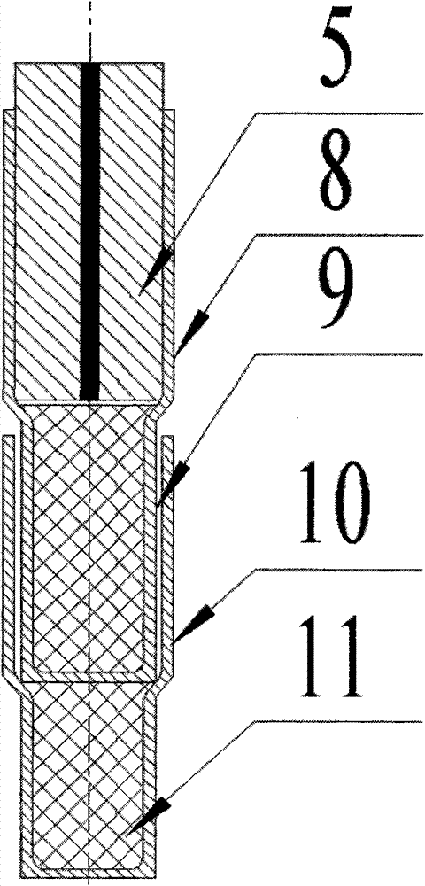
[0025] see image 3 , The two-stage variable cross-section flyer type excitation device is formed by axially stacking and combining two variable cross-section inner caps. All four medicines are housed in the lower cylindrical body 9 of the inner cap above and the lower cylindrical body 11 of the inner cap below. The lower cylindrical body 9 of the upper inner cap is inserted into the upper cylindrical body 10 of the lower inner cap, and the bottom edge of the lower cylindrical body 9 cooperates with the step of the upper cylindrical body 10 . The extension body 5 is arranged in the upper cylindrical body 8 of the upper inner cap. Assembling the two-stage variable-section flyer-type excitation device into the detonator shell constitutes a delay detonator with a two-stage variable-section excitation device.

[0026] Figure 4 It is an embodiment of a non-ele...

Embodiment 3 4

[0029] Embodiment 3 Four-level variable cross-section flyer type excitation device and the detonator using the device

[0030] see Figure 5 , The four-stage variable cross-section flyer type excitation device is composed of four variable cross-section inner caps axially stacked and combined, and its structure is similar to the two-stage excitation device. Each variable cross-section inner cap is equipped with four charges in the lower cylinder. For the instant detonator, there is no delay body; for the delay detonator, the delay body is installed in the upper cylinder of the uppermost inner cap. Assembling the four-stage variable-section flyer-type excitation device into the detonator shell constitutes a delay detonator with a four-stage variable-section excitation device.

[0031] Figure 6 It is an embodiment of a non-electric delay detonator with a four-stage variable cross-section flyer type excitation device. The length of the detonator shell is 90mm. There are three...


PUM


Abstract

The invention relates to a detonator exploding device and a detonator without initiating explosives. The exploding device is at least provided with an inner cap filled with trace explosives, and the inner cap is of a cylindrical structure with varying sections; the outside diameter and the inner bore of the cylinder are both of a big-end-up staircase, and the inner bore of the upper cylinder is larger than the outside diameter of the lower cylinder. The inner bore of the shell of the detonator is a big-end-up stepped hole, the outside circular surface of the upper cylinder of the exploding device is tightly matched with the large inner bore of the shell of the detonator, the diameter of the lower cylinder is smaller than the diameter a small inner bore of the shell of the detonator, and explosives are filled into each lower cylinder; the inner bores of the upper cylinders at the uppermost parts of an instantaneous electric detonator and a non-electric detonator are set to be null, andthe inner bore of the upper cylinder and the outside diameter of the delay element at the uppermost part of a delay electric detonator and the non-electric detonator are tightly matched with each other. The exploding device is accurate to position and can be assembled easily, and the exploding device with single-varying section can be assembled into an exploding device with multi-varying sectionsquickly. When used in the detonator, the exploding device has the advantages of multiply magnified energy, strong initiating ability and capability of initiating high-temperature explosives difficultto initiate, and meets the service requirements under different terrible conditions.

Description

technical field [0001] The invention relates to a detonator excitation device and a non-primer detonator. Background technique [0002] Flyer detonator is a non-priming detonator. It does not use priming during the detonation process. Instead, an inner cap with a small amount of explosive is installed inside the detonator as the initial excitation device. The detonation process is: first ignite the inner cap A small amount of explosives, using the high-temperature and high-pressure gas generated by the explosives in the initial excitation device, breaks the bottom of the inner cap to form flying pieces moving at high speed (600m / s), and the flying pieces hit the low-density explosives at the bottom of the detonator, forming many hot spots to detonate the whole detonator charge. After more than 20 years of hard work, the first generation of flyer detonators (CN1032234) has been gradually perfected and popularized, realizing large-scale automatic production. The first genera...

Claims


Application Information

Patent Timeline
Patent Type & Authority Patents(China)
IPC IPC(8): F42C19/10F42C19/08
Inventor 沈兆武马宏昊
Owner UNIV OF SCI & TECH OF CHINA
Learn More