Top and bottom composite rapping electric dust collector with variable rapping strength

A top-bottom composite, electrostatic precipitator technology, applied in the direction of external electrostatic separator, electrostatic separation, electrode cleaning, etc., can solve the problems of too small preset rapping force, anode plate dust accumulation, dust layer separation, etc. Simple, easy to make, cleverly conceived effects

Inactive Publication Date: 2010-09-15
CHONGQING UNIV +1
View PDF4 Cites 8 Cited by
  • Summary
  • Abstract
  • Description
  • Claims
  • Application Information

AI Technical Summary

Problems solved by technology

[0002] The traditional top-bottom composite rapping electrostatic precipitator includes anode plate, support beam, support plate, top rapping anvil, rapping rod and bottom rapping anvil, wherein the support beam is set on the top of the anode plate, and the support beam is set on the top of the support beam. There is the support plate, the top rapping anvil and the first rapping device are installed on the support plate, and the first rapping device is located at the rear of the top rapping anvil; the bottom of the anode plate is provided with the rapping The left end of the rapping rod is provided with a bottom rapping anvil, and a second rapping device is provided on the left side of the bottom rapping anvil. The second rapping device has the same structure as the first rapping device. The beating device includes a base, a hammer arm and a hammer head, wherein the hammer arm is hinged on the base, and the hammer head is installed at the lower part of the hammer arm, and the quality of the hammer head and the length of the hammer arm are determined at the beginning of the design. Generally, they cannot be

Method used


Image

  • Top and bottom composite rapping electric dust collector with variable rapping strength
  • Top and bottom composite rapping electric dust collector with variable rapping strength
  • Top and bottom composite rapping electric dust collector with variable rapping strength

Examples


Embodiment 1

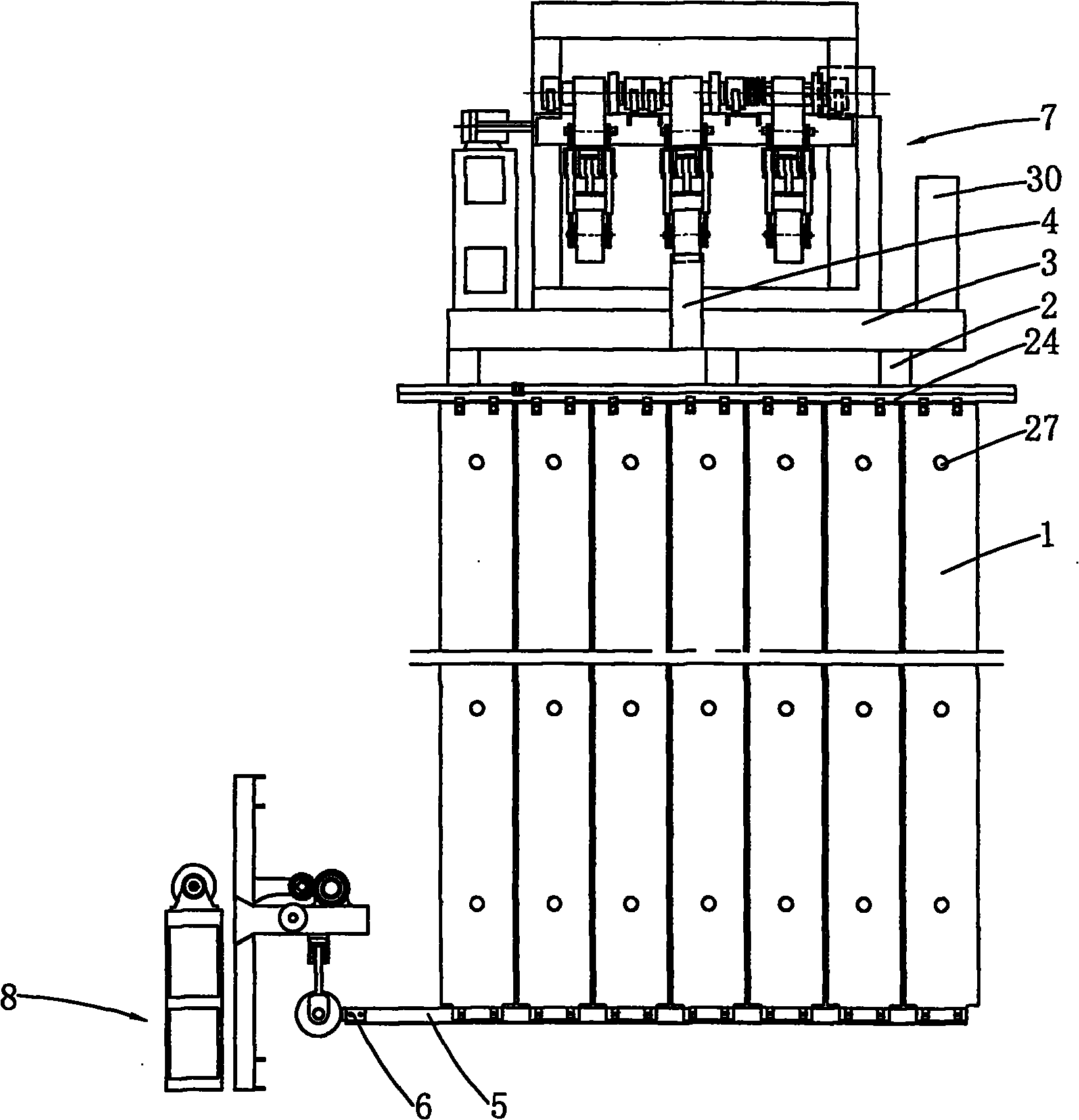
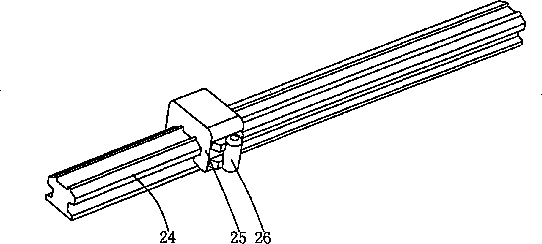
[0034] Such as Figure 1~2 As shown, a top-bottom composite rapping electrostatic precipitator with variable rapping intensity includes an anode plate 1, a support beam 2, a support plate 3, a top rapping anvil 4, a rapping rod 5, a bottom rapping anvil 6, The first rapping device 7, the second rapping device 8 and the computer system 30 are composed of parts such as, wherein an acceleration sensor 27 is arranged on the body of the anode plate 1, and a support beam 2 and a horizontal beam 24 are arranged on the top of the anode plate 1 . The support beam 2 is provided with the support plate 3, the top rapping anvil 4, the computer system 30 and the first rapping device 7 are installed on the support plate 3, and the first rapping device (7) is positioned at the top rapping At the rear of the anvil (4), the computer system (30) is located on the right side of the first rapping device (7). The cross-section of the horizontal beam 24 is "I"-shaped, and a mounting seat 25 is loo...

Embodiment 2

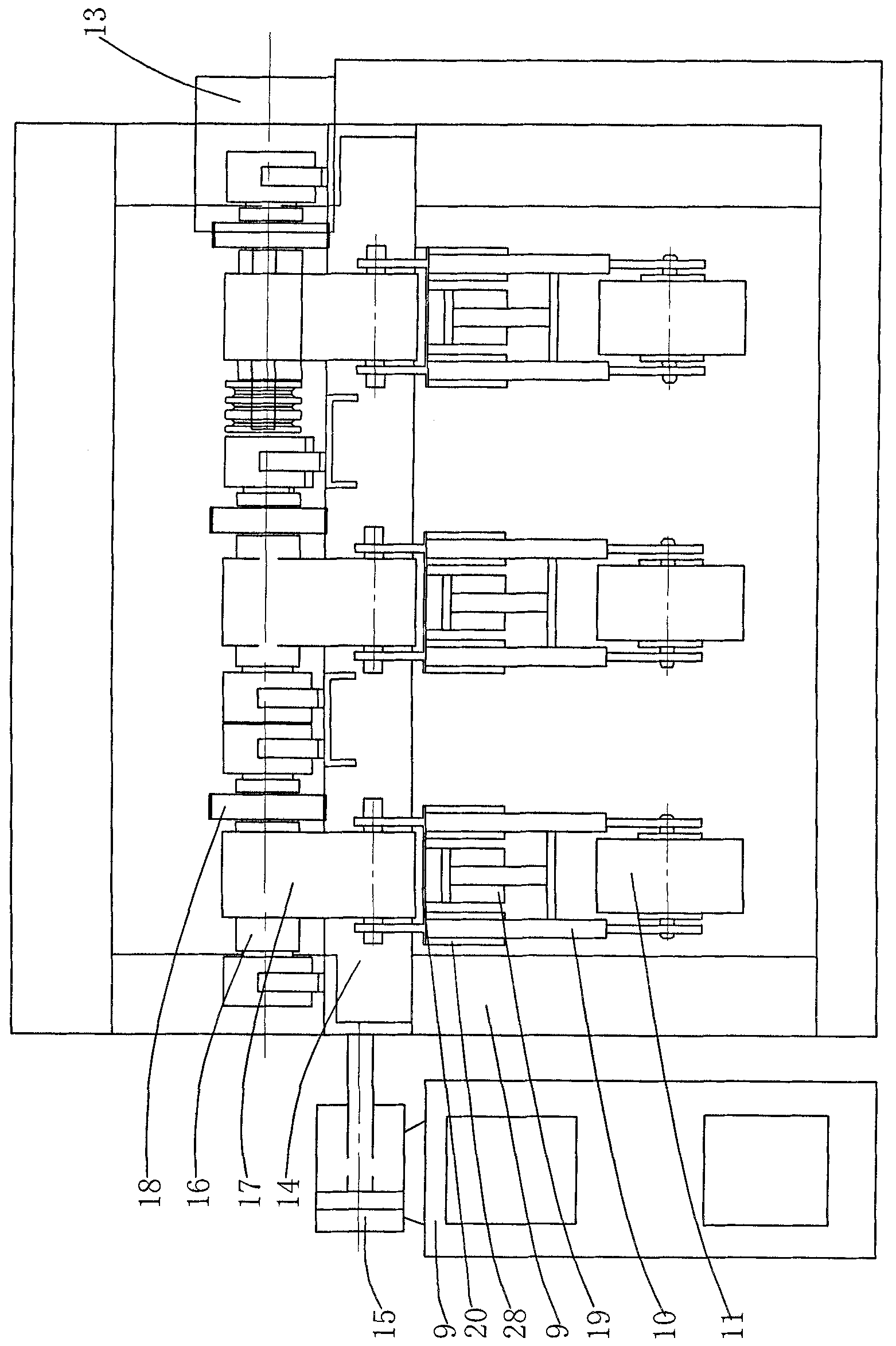
[0050] Such as Figure 8 As shown, at least 3 rapping units are arranged side by side on the mounting base 14 from left to right. In this embodiment, the number of rapping units is 4, and the specific number can be adjusted accordingly according to the actual situation. The rest of the structure of the example is exactly the same as that of the first example, and will not be repeated here.


PUM


Abstract

The invention discloses a top and bottom composite rapping electric dust collector with variable rapping strength, comprising an anode plate, wherein a first rapping device and a computer system are arranged at the top of the anode plate, a second rapping device is arranged at the bottom of the anode plate, has the same structure with the first rapping device and comprises a base, wherein a core shaft, a motor, a mounting seat and a driving hydraulic cylinder are arranged on the base, and a piston rod extension end of the driving hydraulic cylinder is fixed with the mounting seat; rapping units are arranged on the mounting seat side by side, wherein each rapping unit comprises a crank arm shaft, a crank arm, a driven gear, a hydraulic cylinder, a mounting plate, hammer arms and a hammer head, wherein the crank arm and the driven gear are sleeved on the crank arm shaft, the piston rod extension end of the hydraulic cylinder is fixed with the hammer arms, and the hammer head is arrangedbetween the two hammer arms; each rapping unit has the same number with driven gears, and the weights of the hammers are different, wherein one driven gear is engaged. The invention has smart design and simple structure, can regulate the rapping strength according to factors of dust formation thickness, and the like, and can be used for cleaning dust thoroughly without causing secondary dust raise.

Description

technical field [0001] The invention relates to an electric precipitator, in particular to a top-bottom composite rapping electric precipitator with variable rapping intensity. Background technique [0002] The traditional top-bottom composite rapping electrostatic precipitator includes anode plate, support beam, support plate, top rapping anvil, rapping rod and bottom rapping anvil, wherein the support beam is set on the top of the anode plate, and the support beam is set on the top of the support beam. There is the support plate, the top rapping anvil and the first rapping device are installed on the support plate, and the first rapping device is located at the rear of the top rapping anvil; the bottom of the anode plate is provided with the rapping The left end of the rapping rod is provided with a bottom rapping anvil, and a second rapping device is provided on the left side of the bottom rapping anvil. The second rapping device has the same structure as the first rappin...

Claims


Application Information

Patent Timeline
IPC IPC(8): B03C3/04B03C3/76B03C3/34
Inventor 邵毅敏熊绍武祝志芳雷钦平郭廷立万亮华涂文兵陈迅张理全梁省秋黄莺
Owner CHONGQING UNIV
Why Eureka
Try Eureka