Dust-containing gas conveying pipeline and dust-containing gas conveying method

A technology for conveying pipelines and gas, which is applied in the field of dusty gas transportation and filtration. It can solve the problems of pipeline blockage, secondary dust emission, temperature distribution, etc., and achieve the effects of small scouring force, easy dust removal, and difficulty in pipeline blockage.

Pending Publication Date: 2020-05-15
CHENGDU INTERMENT TECH
View PDF0 Cites 0 Cited by
  • Summary
  • Abstract
  • Description
  • Claims
  • Application Information

AI Technical Summary

Problems solved by technology

[0003] The main purpose of the present invention is to provide a pipeline for conveying dusty gas and a method for conveying dusty gas, so as to solve the technical problems of pipeline blockage in the transportation of dusty gas in the prior art and secondary dust raising and temperature distribution in the dust collector

Method used


Image

  • Dust-containing gas conveying pipeline and dust-containing gas conveying method
  • Dust-containing gas conveying pipeline and dust-containing gas conveying method
  • Dust-containing gas conveying pipeline and dust-containing gas conveying method

Examples


Embodiment 1

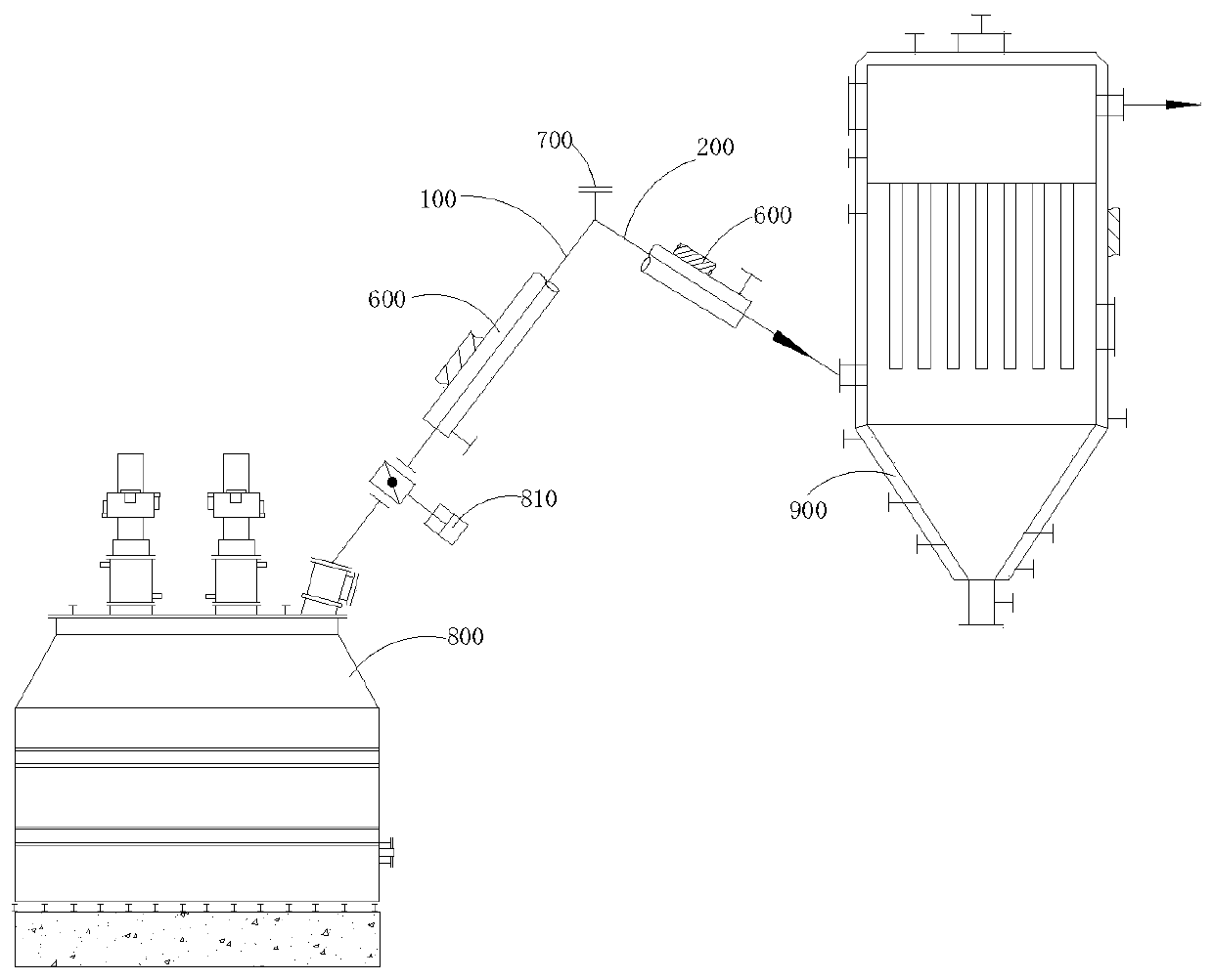
[0044] Such as figure 1 The shown dust-laden gas conveying pipeline connecting the dust-laden gas generating equipment 800 and the dust collector 900, along the conveying direction of the dust-laden gas, the conveying pipeline includes a first ascending pipe 100 and a first descending pipe 200 connected in sequence, so The input end of the first ascending pipe 100 is connected to the gas outlet of the dust-laden gas generating device 800, and the output end of the first descending pipe 200 is connected to the air inlet of the dust collector 900 in the direction toward the lower part of the dust collector 900. , the junction of the first ascending pipe 100 and the first descending pipe 200 forms an obtuse downward angle.

[0045] A soot removal device is provided on the conveying pipeline, and the soot removal device includes a soot removal hole 700 located at the junction of the first riser 100 and the first downcomer 200; the soot removal hole 700 is a fast Open the hand hol...

Embodiment 2

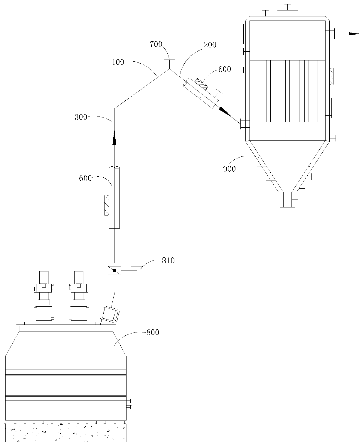
[0050] Compared with Embodiment 1, the difference that the dust-laden gas conveying pipeline of the present embodiment has is: as figure 2As shown, a second riser 300 is provided between the first riser 100 and the gas outlet of the dusty gas generating equipment 800, the second riser 300 is placed vertically, and the first riser 100 and the second riser The included angle between the two ascending pipes 300 is an obtuse angle; at this time, the air intake valve 810 is arranged on the second ascending pipe 300 .

Embodiment 3

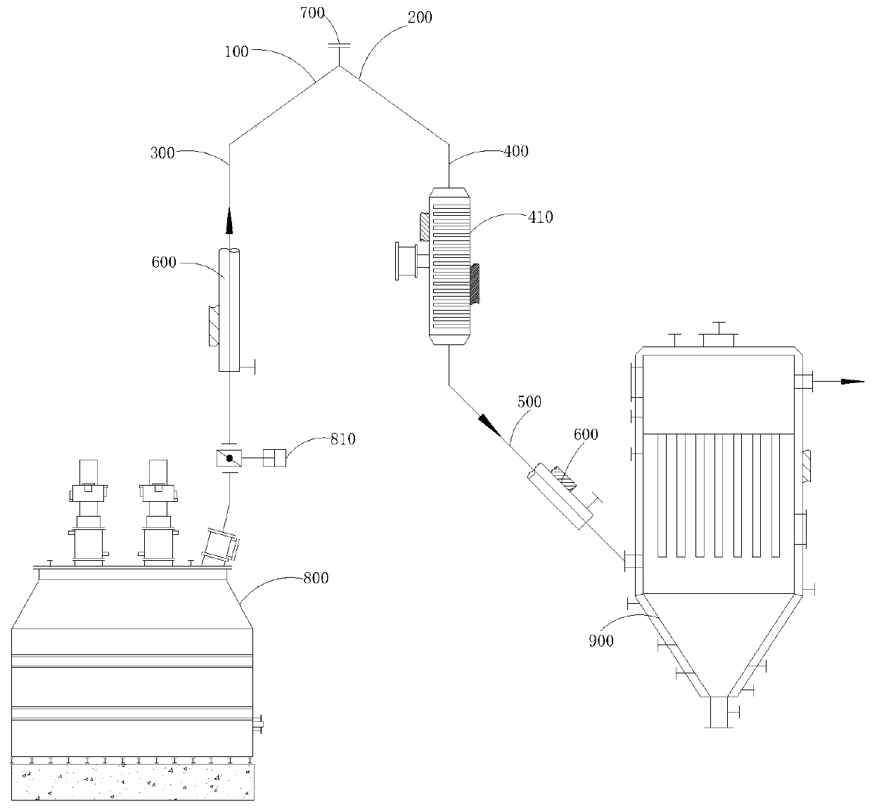
[0052] Compared with embodiment 2, the difference that the dust-laden gas conveying pipeline of the present embodiment has is: as image 3 As shown, a second downcomer is provided between the first downcomer 200 and the air inlet of the dust collector 900, and the second downcomer includes:

[0053] The first pipe body 400, the first pipe body 400 is connected with the first descending pipe 200, and the first pipe body 400 is placed vertically;

[0054] The second pipe body 500 is arranged between the first pipe body 400 and the air inlet of the dust collector 900 .

[0055] The included angle between the first descending pipe 200 and the first pipe body 400 is an obtuse angle;

[0056] The included angle between the first tube body 400 and the second tube body 500 is an obtuse angle.

[0057] A heating device 410 for heating the dust-containing gas is provided on the first pipe body 400 , and the heating tube of the heating device 410 is perpendicular to the conveying direc...


PUM


Abstract

The invention discloses a dust-containing gas conveying pipeline and a dust-containing gas conveying method. The dust-containing gas conveying pipeline comprises a first ascending pipe and a first descending pipe, wherein the input end of the first ascending pipe is connected to a gas outlet of dust-containing gas generation equipment, the output end of the first descending pipe is connected to agas inlet of a dust collector in a direction facing the lower part of the dust collector, and an obtuse angle opened downward is formed at the connection of the first ascending pipe and the first descending pipe. The conveying pipeline is free of a pipe body which is horizontally arranged, so that it is unlikely to cause a pipeline plugging problem, and therefore, the deashing frequency can be reduced. As the pipe body is not arranged horizontally, solid particle impurities deposited in the pipeline during deashing are easier to move, so that it is easier to deash. The output end of the firstdescending pipe is connected to the gas inlet of the dust collector in the direction facing the lower part of the dust collector, so that the dust-containing gas entering the dust collector has a downward moving tendency. The dust-containing gas conveying pipeline is small in scouring vigor to a filter structure, and avoids problems of reentrainment of dust and temperature distribution.

Description

technical field [0001] The invention relates to the technical field of dust-laden gas transportation and filtration, in particular, to a dust-laden gas conveying pipeline and a dust-laden gas conveying method. Background technique [0002] Combustion of substances in the combustion furnace usually produces a large amount of dusty gas, which needs to be dedusted before being discharged. Dust-laden gas is usually transported by a pipe connecting the outlet of the burner and the inlet of the dust collector before entering the dust collector. Due to the geographical difference between the combustion furnace and the dust collector, the pipeline either uses a single pipe body to directly connect the gas outlet of the combustion furnace and the air inlet of the dust collector, or uses a combination of vertical pipe body and horizontal pipe body, which is easy to cause the following Three problems: 1. The output end of the pipeline is set upwards, so that the dusty gas entering the...

Claims


Application Information

Patent Timeline
Patent Type & Authority Applications(China)
IPC IPC(8): F23J3/02F23J11/00F23J15/02F23J15/06F23J15/08F16L53/30
CPCF16L53/30F23J3/02F23J11/00F23J15/022F23J15/025F23J15/06F23J15/08
Inventor 高麟吴志强
Owner CHENGDU INTERMENT TECH
Why Eureka
Try Eureka