
Downhole cooling air-cooling dehumidifier

A dehumidifier and air cooling technology, applied in the direction of heat exchanger shell, indirect heat exchanger, heat exchanger type, etc., can solve the problems of small fluid resistance, large resistance of cooling dehumidifier, low heat transfer coefficient, etc. The difference of heat coefficient, the effect of increasing the heat exchange area on the liquid side and increasing the heat exchange area

Active Publication Date: 2012-05-23
SHANDONG BEICHEN MECHANICAL & ELECTRICAL EQUIP
View PDF0 Cites 0 Cited by
  • Summary
  • Abstract
  • Description
  • Claims
  • Application Information

AI Technical Summary

Problems solved by technology

[0003] In order to overcome the shortcomings of the existing cooling dehumidifiers with large resistance and low heat transfer coefficient, the purpose of the present invention is to provide a well cooling air-cooling dehumidifier. Small

Method used


Image

  • Downhole cooling air-cooling dehumidifier
  • Downhole cooling air-cooling dehumidifier
  • Downhole cooling air-cooling dehumidifier

Examples


Embodiment 1

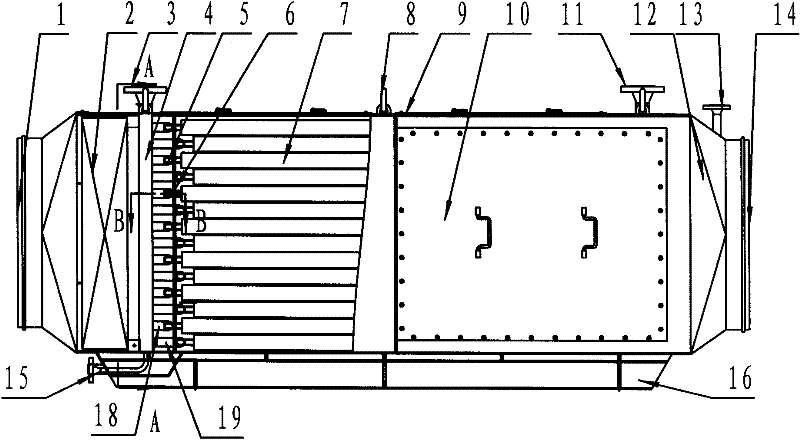
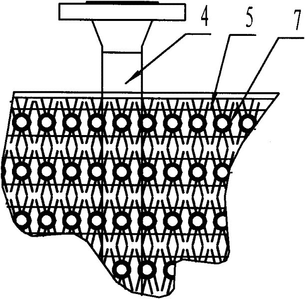
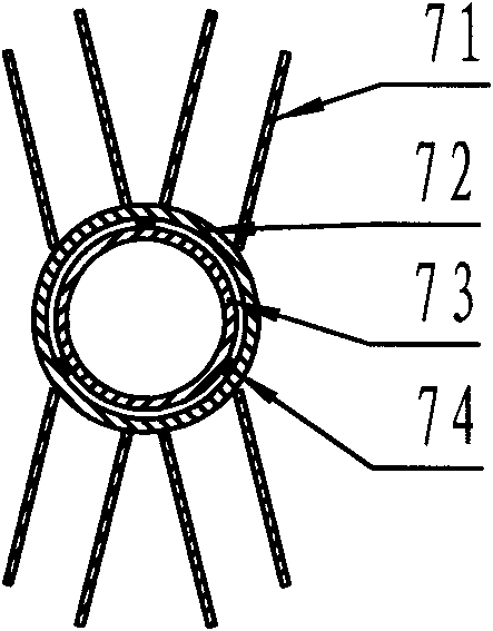
[0019] Embodiment 1, an air-cooled dehumidifier for downhole cooling, including a shell, a heat exchange tube unit 7, a header tube 5, a liquid inlet pipe 4, and a liquid outlet pipe, characterized in that: the heat exchange tube unit is from inside to outside These are the inner tube 73, the outer tube 72, and the fins 71 in sequence. There is a long support bar 74 between the inner tube and the outer tube. The outer tube and the inner tube are gas channels, and the inner tube and the outer tube are liquid flow channels. , each heat exchange tube unit is arranged in a rectangular array, the heat exchange tube unit vertically intersects with the horizontal header tube, the inner tube passes through the header tube, the header tube communicates with the heat exchange tube liquid channel, and the header tube and The liquid inlet and outlet pipes are vertically connected through connecting pipes, and each row of heat exchange tube units is equipped with a support frame 6 . Connec...


PUM


Abstract

The invention discloses a downhole cooling air-cooling dehumidifier, and relates to a heat exchange device for a fixed tubular path assembly of two heat exchange media, in particular to heat exchange equipment which arranges one path in the other path. A heat exchanger comprises a case, heat exchange tube units, a header tube, an inlet tube and an outlet tube. The heat exchanger is characterized in that the heat exchange tube units sequentially comprise an inner tube, an outer tube and a fin from inside to outside, wherein, a long bracing strip is arranged between the inner tube and the outertube, an air path is arranged outside the outer tube and in the inner tube, and a liquid flow channel is arranged between the inner tube and the outer tube; each heat exchange tube unit is arranged in a rectangular array, the heat exchange tube units and the horizontal header tube vertically intersect, and the inner tube extends out of the header tube; the header tube is communicated with the heat exchange tube liquid flow channel, is mutually vertical to the inlet tube and the outlet tube and is connected with the inlet tube and the outlet tube by a connecting tube; and each row of the heat exchange tube units is provided with a support frame. The heat exchanger has large heat exchange area and high heat exchange efficiency and is easy to clean dust and overhaul an inner part.

Description

technical field [0001] The invention pertains to heat exchanging devices for fixed tubular channel assemblies for two heat exchanging media, in particular heat exchanging devices in which one channel is arranged inside the other. Background technique [0002] Under the condition of deep mine mining, the ground temperature is rising continuously, and the heat damage is increasing day by day, which seriously affects the efficiency of workers and their physical and mental health, and may even lead to the occurrence of some mine vicious accidents, which brings great harm to mine safety production and daily management. There is a great threat. At present, the temperature is mainly lowered by arranging cooling dehumidifiers in the tunnel passages. Due to the narrow tunnels, the cooling dehumidifiers are required to be small in size and have good heat exchange effects. However, due to the difference between the heat transfer coefficient of gas and liquid by more than 100 times, an...

Claims


Application Information

Patent Timeline
Patent Type & Authority Patents(China)
IPC IPC(8): E21F3/00F28D7/00F28F9/013F28F9/00
Inventor 李本远孙永星徐吉田叶龙
Owner SHANDONG BEICHEN MECHANICAL & ELECTRICAL EQUIP
Learn More